
Zero power consumption standby control circuit and control method

A zero-power consumption standby and control circuit technology, applied in the direction of electrical components, high-efficiency power electronic conversion, output power conversion devices, etc., can solve problems such as inconvenient use and operation, increase cost, affect equipment dimensions and structural design, etc., to achieve The effect of high working reliability, zero standby power consumption, great practical value and market prospect

Active Publication Date: 2021-08-27
SICHUAN CHANGHONG ELECTRIC CO LTD
View PDF3 Cites 0 Cited by
  • Summary
  • Abstract
  • Description
  • Claims
  • Application Information

AI Technical Summary

Problems solved by technology

But even so, based on the standby current of 10uA (microampere), the annual standby power consumption is nearly 90mAh (milliampere hours), which will be a great challenge for devices using batteries, especially button batteries.
Another traditional technical solution to reduce standby power consumption is to add a power button switch to the device. When the device is not required to work, the power is cut off through the button switch. When the device is required to work, press the switch to turn on the power, but additional power is added. The switch is not only inconvenient to use and operate, but also affects the overall size and structural design of the equipment, and also increases the cost. It is not the best solution in practical applications

Method used


Image

  • Zero power consumption standby control circuit and control method
  • Zero power consumption standby control circuit and control method

Examples


Embodiment

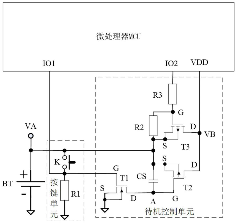
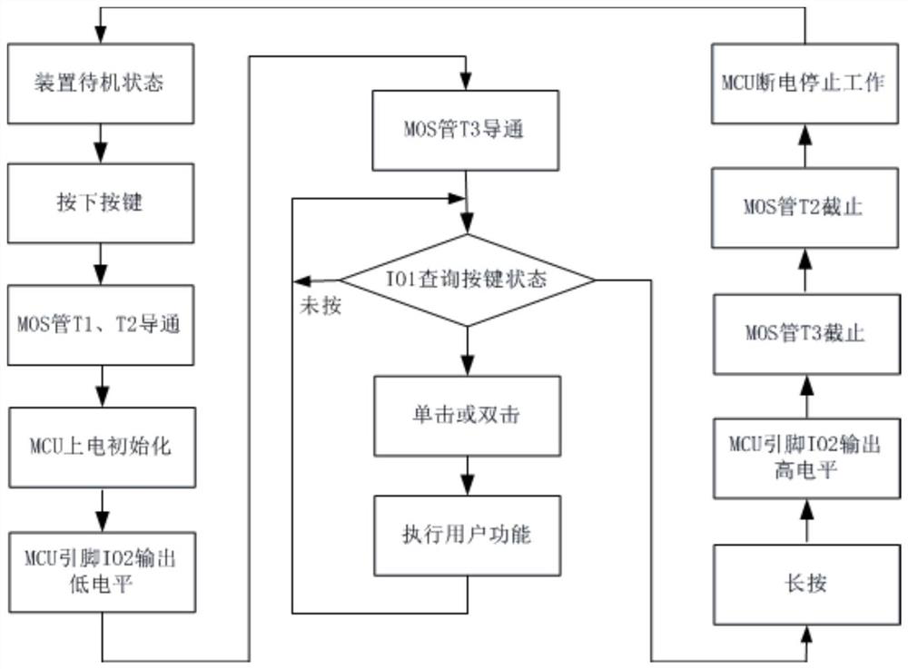
[0019] Such as figure 1 As shown, a zero-power standby control circuit is used for zero-power standby control of smart home equipment, including a microprocessor MCU, a battery BT, a key unit, and a standby control unit, which includes a MOS tube T1, MOS transistor T2 and MOS transistor T3, the gate G of the MOS transistor T1 is connected to the positive terminal VA of the battery BT through the key unit, the source S of the MOS transistor T1 is grounded, and the drain of the MOS transistor T1 D is connected to the gate G of the MOS transistor T2, the source S of the MOS transistor T2 is connected to the source S of the MOS transistor T3 and then connected to the positive terminal VA of the battery BT, and the drain D of the MOS transistor T2 is connected to the positive terminal VA of the battery BT. The drain D of the MOS transistor T3 is connected to the power input terminal VDD of the microprocessor MCU, a storage capacitor CS is connected between the grid G ​​of the MOS t...


PUM


Abstract

The invention discloses a zero-power standby control circuit, which is used for zero-power standby control of smart home equipment, including a microprocessor MCU, a battery BT, a key unit, and a standby control unit, the standby control unit includes a MOS Tube T1, MOS tube T2 and MOS tube T3, the function key K of the key unit is connected to the pin IO1 of the microprocessor MCU, and is used to detect the pressing state of the function key K; the invention also discloses a zero The control method of the power consumption standby control circuit; the invention can completely disconnect the energy consumption components when the equipment is in standby, and truly realize the zero standby power consumption of the system, thereby prolonging the battery life to the maximum extent.

Description

technical field [0001] The invention relates to the field of smart home technology, in particular to a zero-power consumption standby control circuit and control method for smart home equipment. Background technique [0002] With the development of smart home, battery-powered intelligent devices such as smart doorbells, security emergency callers, and portable vacuum cleaners have been more and more widely used. major technical issues. However, such devices tend to work less frequently and each time they work for a shorter duration, and are in a standby state most of the time. Therefore, during the battery life cycle, the power consumption of the device during standby cannot be ignored. Reducing standby power consumption has become the key to extending battery life. The existing technology generally uses an ultra-low power intelligent processor. When the device is in standby, the processor puts all other functional modules of the device in a state of stopping work, and onl...

Claims


Application Information

Patent Timeline
Patent Type & Authority Patents(China)
IPC IPC(8): H02M1/00
CPCH02M1/00H02M1/0035Y02B70/10
Inventor 田朝勇魏劲超
Owner SICHUAN CHANGHONG ELECTRIC CO LTD
Learn More