
Multifunctional transient electroluminescence measuring system

A measurement system and multi-functional technology, applied in the field of spectral measurement and electroluminescence, can solve the problem of low carrier mobility, and achieve the effect of increasing functionality and reducing the required cost

Pending Publication Date: 2021-02-19
HENAN NORMAL UNIV
View PDF0 Cites 0 Cited by
  • Summary
  • Abstract
  • Description
  • Claims
  • Application Information

AI Technical Summary

Problems solved by technology

Provide a square wave voltage pulse to the device through an electric pulse generator, and the device will generate a time-dependent electroluminescent signal. Due to the low carrier mobility of the organic semiconductor material, the time when the device starts to emit light is related to the pulse The voltage has a certain time delay. This delay is generally considered to be related to the mobility of minority carriers in light-emitting devices, so that the mobility of minority carriers can be determined through this delay. However, there is no perfect system on the market now. The spectral image obtained by measuring electroluminescence and the waveform of the corresponding electrical signal, therefore, it is urgent to design a multifunctional transient electroluminescence measurement system to solve the above problems

Method used


Image

  • Multifunctional transient electroluminescence measuring system
  • Multifunctional transient electroluminescence measuring system
  • Multifunctional transient electroluminescence measuring system

Examples


Embodiment Construction

[0016] The following will clearly and completely describe the technical solutions in the embodiments of the present invention with reference to the accompanying drawings in the embodiments of the present invention. Obviously, the described embodiments are only some, not all, embodiments of the present invention. Based on the embodiments of the present invention, all other embodiments obtained by persons of ordinary skill in the art without making creative efforts belong to the protection scope of the present invention.

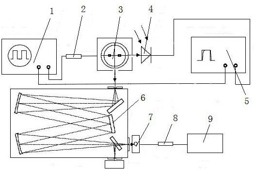
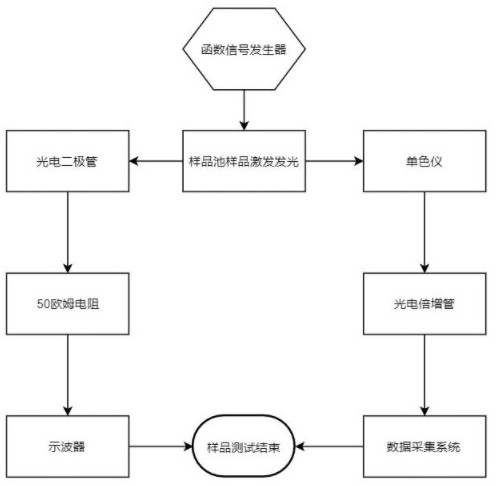
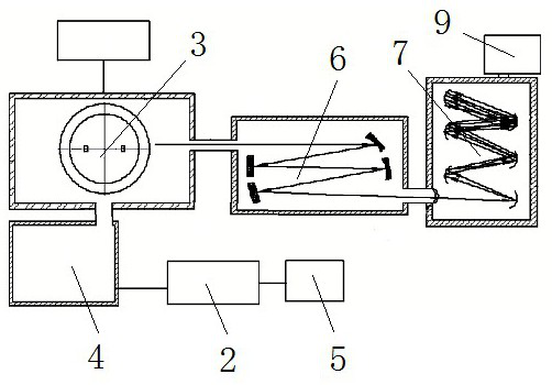
[0017] see Figure 1-3 , the present invention provides a technical solution: a multifunctional transient electroluminescence measurement system, including a function generator 1, a sample resistance 2, a sample cell 3, a photodiode 4, an oscilloscope 5, a monochromator 6, a photomultiplier Tube 7 and computer 9, sample cell 3 is connected with sample resistance one 2 by wire, sample resistance one 2 is connected with function generator 1 by wire, and sample c...


PUM


Abstract

The invention discloses a multifunctional transient electroluminescence measurement system, which comprises a function generator, a sample resistor I, a sample cell, a photodiode, an oscilloscope, a monochromator, a photomultiplier and a computer, and is characterized in that the sample cell is connected with the sample resistor I through a conducting wire, the sample resistor I is connected withthe function generator through a conducting wire, the sample cell is connected with the photodiode through a conducting wire, the photodiode is connected with the oscilloscope through a conducting wire, the function generator is connected with the oscilloscope through a conducting wire, the monochromator corresponds to the sample cell, the monochromator is connected with the photomultiplier through a conducting wire, and the photomultiplier is connected with the computer through a conducting wire. According to the invention, a traditional single and complex spectrum or waveform measuring system is changed, the two functions are ingeniously combined into a whole, a grating spectrometer composed of a monochromator and a photomultiplier is used for replacing a spectrometer high in price, theexperiment effect can be achieved as well, and the needed cost of the system is greatly reduced.

Description

technical field [0001] The invention relates to the technical fields of spectrum measurement and electroluminescence, in particular to a multifunctional transient electroluminescence measurement system. Background technique [0002] Transient electroluminescence, transient electroluminescence is a method of measuring electrical pulses. A square wave voltage pulse is provided to the device through an electric pulse generator, and the device will generate a time-dependent electroluminescent signal. Due to the low carrier mobility of the organic semiconductor material, the time when the device starts to emit light is related to the pulse The voltage has a certain time delay. This delay is generally considered to be related to the mobility of minority carriers in light-emitting devices, so that the mobility of minority carriers can be determined through this delay. However, there is no perfect system on the market that can The spectrum image obtained by measuring electrolumines...

Claims


Application Information

Patent Timeline
Patent Type & Authority Applications(China)
IPC IPC(8): G01N21/66G01N21/01
CPCG01N21/01G01N21/66G01N2021/0112
Inventor 郭嘉辉秦朝朝谢萌冉李嫣然王新元
Owner HENAN NORMAL UNIV
Learn More