
Three-point/four-point bending fatigue test method and device for composite material

A four-point bending, composite material technology, used in measuring devices, analyzing materials, and testing the strength of materials by applying a stable bending force. constraints, etc.

Pending Publication Date: 2021-02-19
BEIJING AERONAUTIC SCI & TECH RES INST OF COMAC +1
View PDF0 Cites 3 Cited by
  • Summary
  • Abstract
  • Description
  • Claims
  • Application Information

AI Technical Summary

Problems solved by technology

However, the existing three-point / four-point bending static test fixtures for composite materials lack the normal direction of the loading direction and the boundary constraints along the length direction of the specimen, and cannot restrain specimens of different sizes. Out-of-plane and lateral slippage will occur, resulting in changes in the loading position of the test piece, and the accuracy of the test results cannot be guaranteed
[0003] In the prior art composite material test, the three-point / four-point bending fatigue test fixture of the sandwich structure is mostly carried out by the static test test fixture; for the three-point / four-point bending fatigue test with special requirements, the special fixture is used for the test, and it is impossible Guarantee the accuracy of test results

Method used


Image

  • Three-point/four-point bending fatigue test method and device for composite material
  • Three-point/four-point bending fatigue test method and device for composite material
  • Three-point/four-point bending fatigue test method and device for composite material

Examples


Embodiment Construction

[0044] In order to better understand the technical solutions of the present invention, the embodiments of the present invention will be described in detail below in conjunction with the accompanying drawings.

[0045] It should be clear that the described embodiments are only some of the embodiments of the present invention, not all of them. Based on the embodiments of the present invention, all other embodiments obtained by persons of ordinary skill in the art without creative efforts fall within the protection scope of the present invention.

[0046] Terms used in the embodiments of the present invention are only for the purpose of describing specific embodiments, and are not intended to limit the present invention. As used in the embodiments of the present invention and the appended claims, the singular forms "a", "said" and "the" are also intended to include the plural forms unless the context clearly indicates otherwise.

[0047] Such as Figure 2-Figure 5 Shown, a kind...


PUM


Abstract

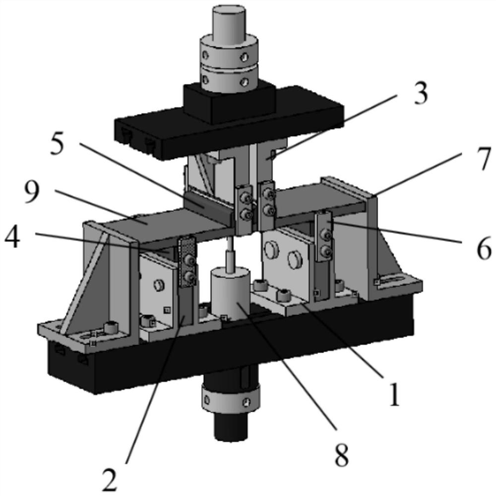
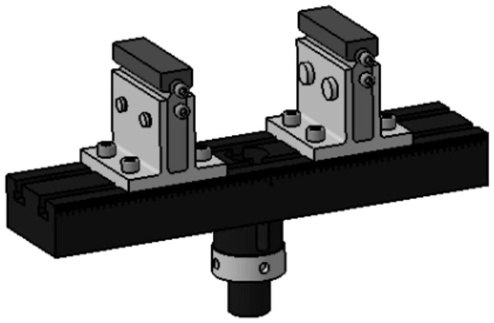
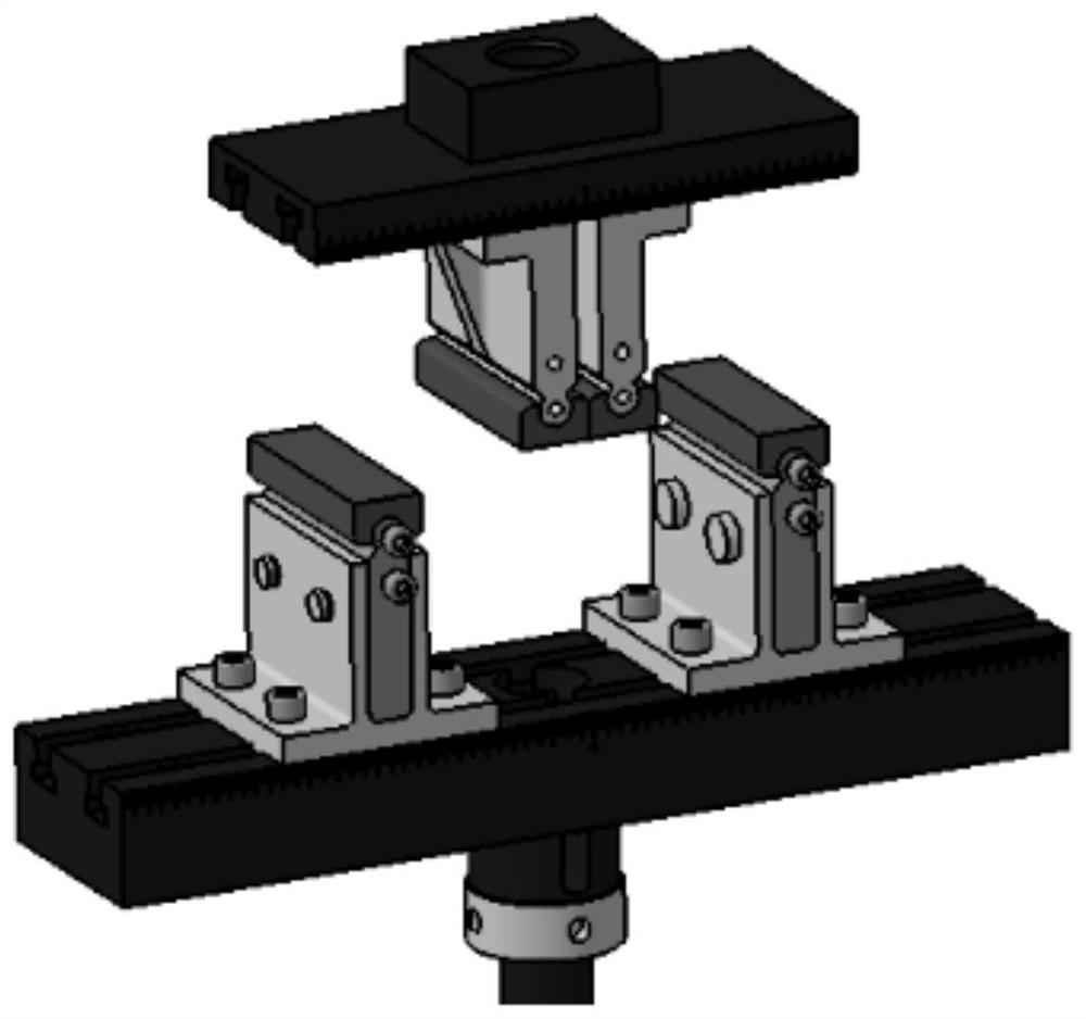
The invention provides a three-point / four-point bending fatigue test method and device for a composite material. The device comprises an upper loading roller which is used for restraining the verticalupward normal deviation of a test piece in a loading direction, a lower supporting roller which is used for constraining the vertical downward normal deviation of the test piece in the loading direction, a transverse baffle which is used for restraining transverse deviation of the test piece in the length direction, a side baffle plate which is used for restraining the longitudinal deviation of the test piece along the width direction and fixing the upper loading roller and the lower supporting roller at the same time, a lower supporting base which is used for supporting the lower supportingroller, a lower supporting block which is arranged between the lower supporting base and the lower supporting roller, and is used for changing the distance between the lower supporting roller and theupper loading roller by changing the size of the lower supporting block, a lower bottom plate which is used for supporting the lower supporting base and the transverse baffle, and a displacement meterwhich is fixedly connected to the lower bottom plate. The bending deformation of the test piece is measured through the displacement meter.

Description

【Technical field】 [0001] The invention relates to the technical field of material performance testing, in particular to a composite material three-point / four-point bending fatigue test method and device. 【Background technique】 [0002] Composite materials have the advantages of high specific strength and high specific stiffness, strong designability and good fatigue performance. Its bending performance is also a performance that needs to be considered in the design and use of composite materials. However, the existing three-point / four-point bending static test fixtures for composite materials lack the normal direction of the loading direction and the boundary constraints along the length direction of the specimen, and cannot restrain specimens of different sizes. Out-of-plane and lateral slippage will occur, resulting in changes in the loading position of the test piece, and the accuracy of the test results cannot be guaranteed. [0003] In the prior art composite material...

Claims


Application Information

Patent Timeline
IPC IPC(8): G01N3/20
CPCG01N3/20G01N2203/0003G01N2203/0023G01N2203/0073G01N2203/0682
Inventor 张达王学朋张俊琪苑静宇李萌冯荣欣
Owner BEIJING AERONAUTIC SCI & TECH RES INST OF COMAC
Learn More