Self-locking nut structure of gas turbine rotor shaft

A technology of self-locking nuts, gas turbines, applied in the direction of nuts, screws, bolts, etc.

Inactive Publication Date: 2021-02-19
HARBIN GUANGHAN GAS TURBINE
View PDF5 Cites 1 Cited by
  • Summary
  • Abstract
  • Description
  • Claims
  • Application Information

AI Technical Summary

Problems solved by technology

[0003] The purpose of the present invention is to provide a self-locking nut structure of a gas turbine rotor shaft that can solve the fastening problem between the gas turbine compressor rotor and the turbine rotor

Method used


Image

  • Self-locking nut structure of gas turbine rotor shaft

Examples


Embodiment Construction

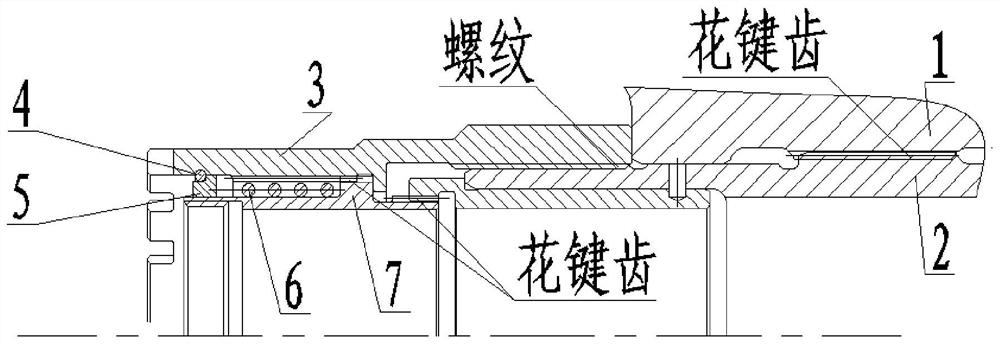
[0011] The present invention is described in more detail below in conjunction with accompanying drawing example:

[0012] combine figure 1 , The self-locking nut structure of a gas turbine rotor shaft in the present invention includes a compressor rotor 1, a turbine rotor 2, a shaft nut 3, a support ring 4, a stop ring 5, a spring 6, and a stop sleeve 7. The turbine rotor 2 passes through the inner hole of the compressor rotor 1, and the inner splines of the compressor rotor 1 cooperate with the outer splines of the turbine rotor 2 to realize the torque transmission from the turbine rotor 2 to the compressor rotor 1 during gas operation. A matching positioning dimension with a small gap is designed between the compressor rotor 1 and the turbine rotor 2 .

[0013] The inner thread of the sleeve nut 3 cooperates with the outer thread of the turbine rotor 2 to realize the fastening of the compressor rotor 1 and the turbine rotor 2 .

[0014] There is a circumferential groove in...


PUM


Abstract

The invention aims to provide a self-locking nut structure of a gas turbine rotor shaft. The self-locking nut structure comprises a sleeve nut, a stop sleeve, a gas compressor rotor and a turbine rotor, wherein the gas compressor rotor is provided with an internal spline, the turbine rotor is provided with an external spline, an internal spline and an external thread, the sleeve nut is provided with an internal thread and an internal spline, and the stop sleeve is provided with a first external spline and a second external spline; the internal spline of the gas compressor rotor is matched withthe external spline of the turbine rotor, the internal thread of the sleeve nut is matched with the external thread of the turbine rotor, the first external spline of the stop sleeve is matched withthe internal spline of the sleeve nut, the second external spline of the stop sleeve is matched with the internal spline of the turbine rotor, and a spring is arranged between the sleeve nut and the stop sleeve; and one end of the spring serves as a protruding part of the stop sleeve, the other end of the spring serves as a stop ring, a groove is formed in an inner hole of the sleeve nut, and a backing ring is installed between the groove and the stop ring. According to the self-locking nut structure, the gas compressor rotor and the turbine rotor can be fastened, and the self-locking effect is achieved.

Description

technical field [0001] The invention relates to a gas turbine, in particular to a self-locking structure of a gas turbine rotor shaft. Background technique [0002] The turbine rotor of the gas turbine transmits torque to the compressor rotor. Usually, the structure is designed such that the turbine rotor passes through the inner hole of the compressor rotor, and the two transmit torque through the interaction between the outer splines of the turbine rotor and the inner splines of the compressor rotor. The design requirements The two are fastened together, and the locking is required not to loosen. During the design process, due to the limitation of structure and space, the structure of the nut is required to have the function of self-locking. Contents of the invention [0003] The object of the present invention is to provide a self-locking nut structure of a gas turbine rotor shaft which can solve the fastening problem between the gas turbine compressor rotor and the tur...

Claims


Application Information

Patent Timeline
Patent Type & Authority Applications(China)
IPC IPC(8): F16B37/00F16B39/02F01D5/02
CPCF16B37/00F16B39/02F01D5/02
Inventor 刘冰冰金鹏衣爽徐宁王廷张舟洪青松
Owner HARBIN GUANGHAN GAS TURBINE
Why Eureka
Try Eureka