Automobile electric power steering control system

A technology of electric power steering and control system, which is applied in the direction of electric steering mechanism, power steering mechanism, steering mechanism, etc., and can solve the problems that the steering feel of the steering column cannot be adjusted, the vehicle is out of control, etc.

Inactive Publication Date: 2021-02-19
XIAN ZHIYUEDA SOFTWARE CO LTD
View PDF2 Cites 0 Cited by
  • Summary
  • Abstract
  • Description
  • Claims
  • Application Information

AI Technical Summary

Problems solved by technology

[0006] The purpose of the present invention is to solve the problems in the prior art that the steering feel of the steering column cannot be adjusted, the steering feel is lighter when the speed of the vehicle is fast, and the driver’s improper operation easily leads to the loss of control of the vehicle, and a kind of automobile electric power steering is proposed. Control System

Method used


Image

  • Automobile electric power steering control system
  • Automobile electric power steering control system

Examples


Embodiment 1

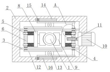
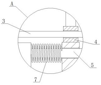
[0023] Example 1 as Figure 1-2 As shown, this automobile electric power steering control system includes a steering shaft 1 and a fixed frame 2, the steering shaft 1 passes through the center of the fixed frame 2, and the fixed frame 2 is symmetrically fixedly connected with a stabilizer bar 3, on which the stabilizer bar 3 The sliding socket has two sliding sleeves 4, and a moving plate 6 is fixedly connected between the corresponding two sliding sleeves 4 on the two stabilizing bars 3, and two springs are fixedly connected to the opposite ends of the two moving plates 6. 7. The other ends of the two springs 7 are fixedly connected with a mounting plate 8. The end of the mounting plate 8 close to the steering shaft 1 is equipped with a damping plate 9. The damping plate 9 is in contact with the steering shaft 1. One of the moving plates 6 A driving mechanism is installed, and a transmission mechanism is installed between the two moving plates 6. When it is necessary to adjus...

Embodiment 3

[0025] Embodiment 3 is such as on the basis of embodiment 1 figure 1 As shown, its transmission mechanism includes four racks 12, the four racks 12 are fixedly connected on the side wall of the sliding sleeve 4, and a gear 13 is arranged between the corresponding two racks 12, and the gear 13 is installed through a rotating shaft On the fixed frame 2, the corresponding two racks 12 are meshed with the gears 13. When one of the moving plates 6 moves, it drives the corresponding rack 12 to move, the rack 12 drives the gear 13 to rotate, and the gear 13 drives the other two gears. A rack 12 moves, and then drives another moving plate 6 to move.

Embodiment 4

[0026] Embodiment 4 is such as on the basis of embodiment 1 figure 1 As shown, its fixed frame 2 is provided with a limit slot 14 at the position corresponding to the rack 12, and the limit block 15 is slidably connected to the limit block 15 in the limit slot 14, and the end of the limit block 15 away from the bottom of the limit slot 14 passes through the limit The notch of the slot 14 extends outward, and is fixedly connected to the corresponding position of the corresponding rack 12, so that the corresponding rack 12 moves more stably.


PUM


Abstract

The invention relates to the technical field of automobile steering, and discloses an automobile electric power steering control system which comprises a steering shaft and a fixing frame; the steering shaft penetrates through the center of the fixing frame, stabilizing rods are symmetrically and fixedly connected into the fixing frame, and two sliding sleeves are slidably connected to the stabilizing rods in a sleeving mode. Moving plates are fixedly connected between the two corresponding sliding sleeves located on the two stabilizing rods, two springs are fixedly connected to the opposite ends of the two moving plates correspondingly, a mounting plate is fixedly connected to the other ends of the two springs jointly, and a damping plate is mounted at the end, close to the steering shaft, of the mounting plate; the damping plate makes contact with the steering shaft, a driving mechanism is installed on one moving plate, and a transmission mechanism is installed between the two movingplates. The hand feeling of the steering shaft can be changed, and different driving conditions can be met.

Description

technical field [0001] The invention relates to the technical field of automobile steering, in particular to an automobile electric power steering control system. Background technique [0002] The electric power steering system is one of the hot topics in the field of automotive engineering. The main content of the current research is the control rules of the EPS system and the design of the hardware controller, and the realization of the control rules must be based on a stable and reliable controller. [0003] In the patent No. CN209505836U, an electric power steering control system for electric vehicles is disclosed, which can collect torque signals and vehicle speed signals in real time, and realize the control of the motor through the direction control circuit, H-bridge motor drive circuit and PWM pulse width modulation technology. control, which greatly simplifies the circuit design and improves the reliability of the system; [0004] In the patent No. CN206367511U, an...

Claims


Application Information

Patent Timeline
Patent Type & Authority Applications(China)
IPC IPC(8): B62D5/04
CPCB62D5/0403B62D5/0409B62D5/0463
Inventor 高燕松
Owner XIAN ZHIYUEDA SOFTWARE CO LTD
Why Eureka
Try Eureka