
Engine dismounting turnover machine

A technology of engine and turning machine, applied in the direction of workbench, manufacturing tools, etc., can solve the problems of poor practicability of the device, cumbersome operation, difficult positioning operation, etc., and achieve the effect of reducing the difficulty of connection and installation, prolonging the service life and enhancing the practicality

Pending Publication Date: 2021-02-19
江苏亚飞机械制造有限公司
View PDF0 Cites 0 Cited by
  • Summary
  • Abstract
  • Description
  • Claims
  • Application Information

AI Technical Summary

Problems solved by technology

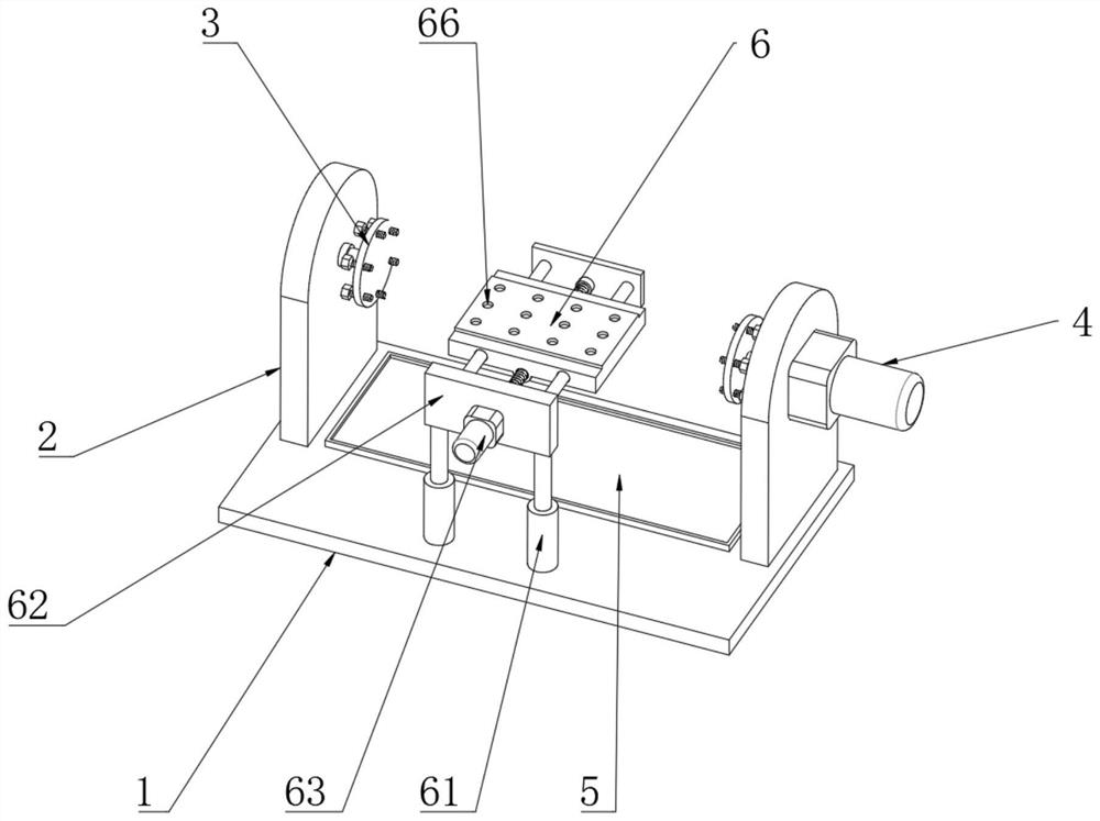
[0003] When the engine is overhauled and disassembled, it is necessary to use the engine disassembly turning machine to fix the turning, so as to facilitate the operation of the user. However, when the current engine disassembly turning machine fixes the engine, it is necessary to use a forklift to lift the engine to the engine disassembly. On the fixing mechanism of the overturning machine, the engine and the overturning machine are connected and fixed by bolts. During the connection process, due to the large size of the forklift, it is difficult to perform precise positioning operations. It is necessary to constantly try positioning, which is cumbersome and time-consuming. The practicality of the device Poor sex

Method used


Image

  • Engine dismounting turnover machine
  • Engine dismounting turnover machine
  • Engine dismounting turnover machine

Examples


Embodiment Construction

[0018] In order to make the technical means, creative features, goals and effects achieved by the present invention easy to understand, the present invention will be further described below in conjunction with specific embodiments.

[0019] In the description of the present invention, it should be noted that the terms "upper", "lower", "inner", "outer", "front end", "rear end", "both ends", "one end", "another end" The orientation or positional relationship indicated by etc. is based on the orientation or positional relationship shown in the drawings, and is only for the convenience of describing the present invention and simplifying the description, rather than indicating or implying that the referred device or element must have a specific orientation, use a specific Azimuth configuration and operation, therefore, should not be construed as limiting the invention. In addition, the terms "first" and "second" are used for descriptive purposes only, and should not be understood ...


PUM


Abstract

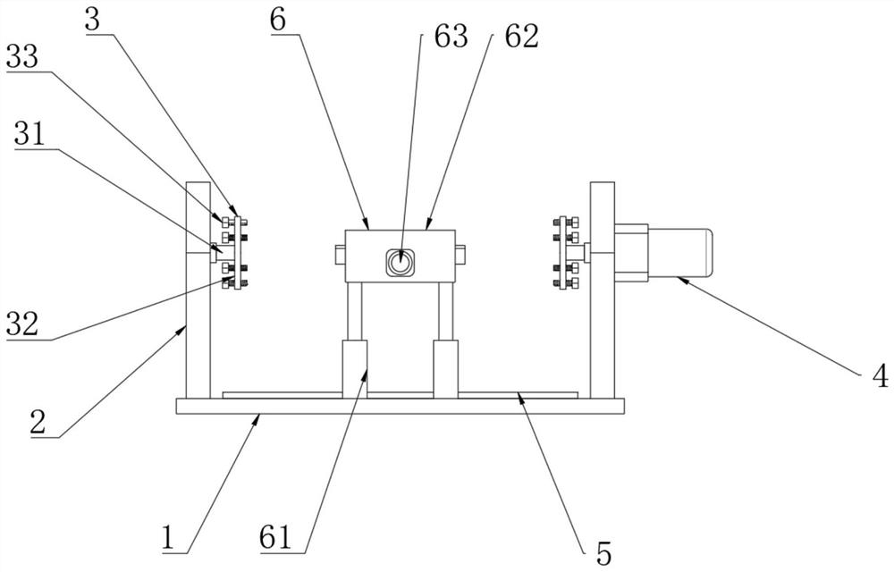
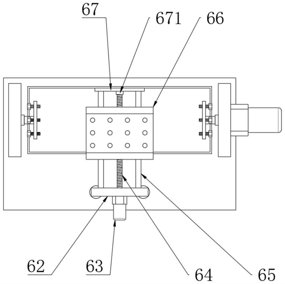
The invention discloses an engine engine dismounting turnover machine. The engine dismounting turnover machine comprises a base, wherein mounting frames are arranged at the top end of the base in a bilateral symmetry mode; fixing mechanisms are rotationally connected to the inner sides of the two mounting frames; each fixing mechanism comprises a connecting shaft; the connecting shafts are rotationally connected to the mounting frames through bearings; a fixed plate is arranged at the end, away from the corresponding mounting frame, of each connecting shaft; a tilt drive motor is arranged at the right end of the mounting frame at the right end; the output end of the tilt drive motor penetrates through the corresponding mounting frame to be connected to the corresponding fixing mechanism; and an auxiliary mounting mechanism is arranged at the front part of the top end of the base. Through the arrangement of the auxiliary mounting mechanism, a forklift and other large instruments do notneed to be used for trying to position for multiple times, the connecting and mounting difficulty of an engine is reduced, the practicability of the device is effectively enhanced, and compared with traditional one-way fixing, the pressure borne by the fixing mechanisms is effectively reduced by adopting the fixing mechanisms arranged in a bilateral symmetry mode for fixing, and the service life of the fixing mechanisms can be effectively prolonged.

Description

technical field [0001] The invention relates to the technical field of engine supporting equipment, in particular to an engine disassembly and turning machine. Background technique [0002] An engine is a machine that can convert other forms of energy into mechanical energy, including internal combustion engines (reciprocating piston engines), external combustion engines (Stirling engines, steam engines, etc.), jet engines, electric motors, etc. For example, internal combustion engines usually convert chemical energy into mechanical energy. The engine is not only applicable to the power generating device, but also refers to the whole machine including the power device. [0003] When the engine is overhauled and disassembled, it is necessary to use the engine disassembly turning machine to fix the turning, so as to facilitate the operation of the user. However, when the current engine disassembly turning machine fixes the engine, it is necessary to use a forklift to lift the...

Claims


Application Information

Patent Timeline
Patent Type & Authority Applications(China)
IPC IPC(8): B25H1/08B25H1/10B25H1/14
CPCB25H1/08B25H1/10B25H1/14
Inventor 孔令飞陈其根
Owner 江苏亚飞机械制造有限公司
Learn More