
Baseball pitching machine

A ball machine and baseball technology, applied to rackets, sports accessories, etc., can solve the problems of electric shock hazard, unfavorable outdoor use, unstable base, etc., achieve easy disassembly and installation, one machine with dual-purpose practicability, and improve the technical level Effect

Pending Publication Date: 2021-02-19
杨磊
View PDF2 Cites 0 Cited by
  • Summary
  • Abstract
  • Description
  • Claims
  • Application Information

AI Technical Summary

Problems solved by technology

[0002] Existing foreign baseball ball machines mostly use AC motors, usually 110 volts of alternating current. When used domestically, a voltage converter is required to convert 220 volts of alternating current to 110 volts of alternating current, and then drive the baseball ball machine to run, which is not conducive to outdoor use. It needs to connect a long wire, which is easy to cause electric shock hazard, and it is extremely inconvenient to use
Other disadvantages are: most of the friction wheels of the baseball ball machine are made of rubber, which wears out quickly
Although the rotation of the launching device is used to deflect the flywheel, thereby launching balls at different angles, there is no disclosure of a technical solution in which the baseball itself has a rotating function, and the angle of inclination of the base used is limited. The angle adjustment device can only adjust the angle of the launcher body and control the height of the ball outlet
In addition, when the height of the control ball outlet is changed, the position of the overall center of gravity changes, and when the ball is served, it is easy to cause the base to become unstable.

Method used


Image

  • Baseball pitching machine
  • Baseball pitching machine
  • Baseball pitching machine

Examples


Embodiment Construction

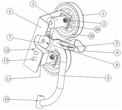
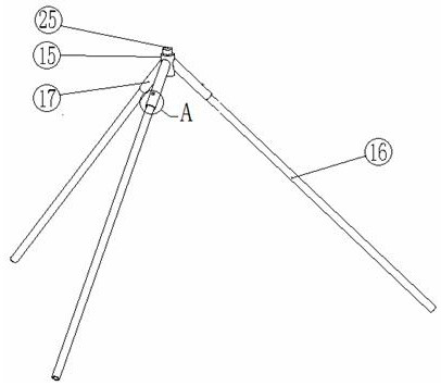
[0037] Such as Figure 1-12As shown, it includes a storage battery 18, an AC / DC power converter 19, an upper part 20, a lower part 21, and a steering part 22 connecting the upper part 20 and the lower part 21. It is characterized in that the upper part includes: Friction wheel 1, flange 2, motor 3, panel 4, goal cylinder bracket 5, goal cylinder 6, corner brace I7, corner brace II8, intermediate bracket 9, connecting sleeve 10, control box 11, power switch 12, Governor 13, wherein, the core of the friction wheel 1 is an aluminum alloy wheel hub, and the aluminum alloy wheel hub is covered with a polyurethane rubber wheel, and the friction wheel 1 and the flange 2 are connected by bolts. The flange 2 is connected with the motor shaft of the motor 3, and the motor 3 is connected with the panel 4 by bolts to increase structural stability; the goal cylinder support 5 is connected with the goal cylinder 6 by bolts, and the progress Bar-shaped grooves are opened on the ball barrel ...


PUM


Abstract

The invention discloses a baseball pitching machine, which mainly comprises a storage battery, an alternating-current and direct-current power converter, an upper mounting part, a lower mounting partand a steering part for connecting the upper mounting part and the lower mounting part, wherein power is supplied to the upper mounting part through any one of the storage battery or the alternating-current and direct-current power converter, pitching is achieved through a friction wheel of the upper mounting part, ball pitching in different directions is achieved through utilizing the steering part, the angle of ball pitching is adjusted by an angle brace I and an angle brace II of the upper mounting part, and the radian of a baseball to be pitched is obtained. The baseball pitching machine has the advantages that the baseball pitching machine is simple in overall structure and easy to disassemble and assemble, the service life of the friction wheel is long, the lower mounting part firmlysupports the upper mounting part, efficient partner training is provided for improving the technical level of baseball players, the baseball pitching machine can be used for launching softballs, andthe baseball pitching machine is dual-purpose and high in practicability.

Description

technical field [0001] The invention relates to the field of sports equipment, in particular to a baseball serving machine. Background technique [0002] Existing foreign baseball ball machines mostly use AC motors, usually 110 volts of alternating current. When used domestically, a voltage converter is needed to convert 220 volts of alternating current to 110 volts of alternating current, and then drive the baseball ball machine to run, which is not conducive to outdoor use. It needs to connect very long wires, which is easy to cause electric shock hazard, and it is extremely inconvenient to use. Other weak points are: the friction wheel of the baseball ball machine is mostly made of rubber, which wears out quickly. Existing baseball machines have limited ability to adjust the speed and angle of the ball, and it is impossible to use the same ball machine to satisfy various speeds and directions. Secondly, the existing baseball serving machine is not easy to disassemble, d...

Claims


Application Information

Patent Timeline
Patent Type & Authority Applications(China)
IPC IPC(8): A63B69/40
CPCA63B69/406A63B2069/402A63B2102/18
Inventor 杨磊朱乃新崔伯阳
Owner 杨磊
Learn More