
Stator winding, motor stator and motor

A technology of stator winding and phase winding, which is applied in the field of stator winding, motor stator and motor, can solve the problems of excessive heat dissipation of bridge wires, low motor power, high loop current, etc., and achieve reduction of bridge wires, high processing efficiency, and production low cost effect

Active Publication Date: 2021-02-12
BORGWARNER POWERDRIVE SYST (TIANJIN) CO CHINA
View PDF10 Cites 1 Cited by
  • Summary
  • Abstract
  • Description
  • Claims
  • Application Information

AI Technical Summary

Problems solved by technology

[0003] The invention provides a stator winding, a motor stator and a motor, and is especially suitable for a stator winding composed of a single U-shaped conductor, which solves the problem of unreasonable structural design of hairpin coils formed by mixed arrangement of multiple conductors in the prior art. The resulting high loop current, many bridge wires and uneven heat dissipation lead to technical problems of low motor power and small torque

Method used


Image

  • Stator winding, motor stator and motor
  • Stator winding, motor stator and motor
  • Stator winding, motor stator and motor

Examples


Embodiment Construction

[0053] The present invention will be described in detail below in conjunction with the accompanying drawings and specific embodiments.

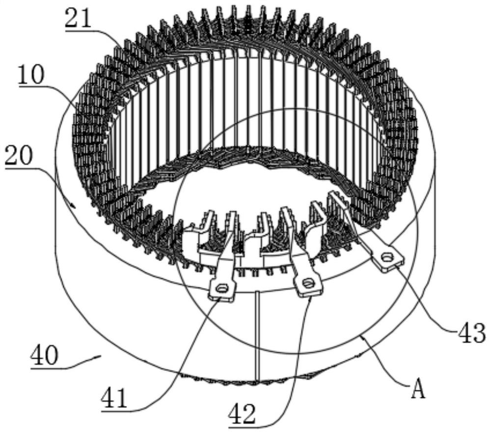
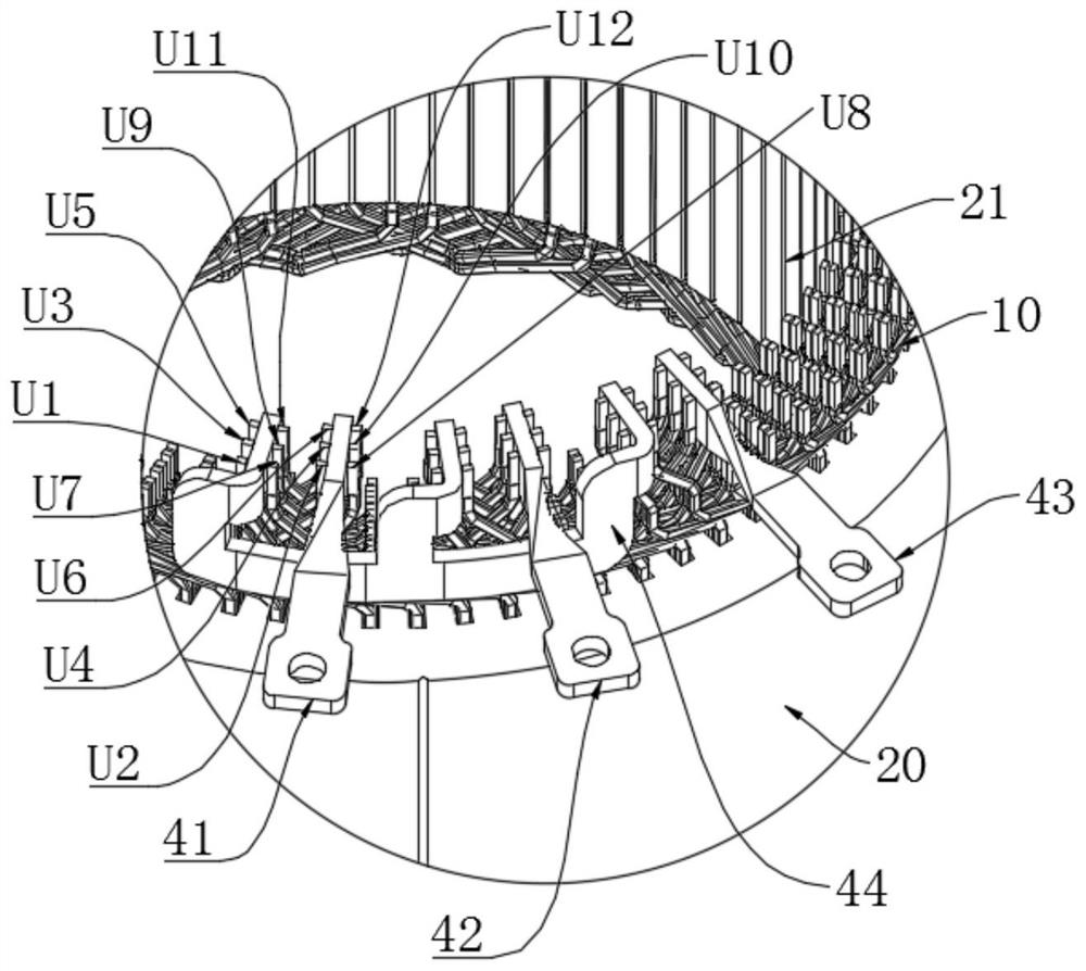
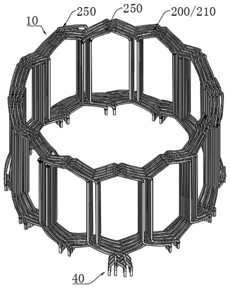
[0054] A stator winding 10 proposed in this embodiment, such as figure 1 , figure 2 with image 3 As shown, installed on the stator core 20, wherein the stator core 20 has a plurality of slots 21, the slots 21 are arranged on the radial inner surface of the stator core 20 and along the circumferential direction of the stator core 20 in a predetermined The slots are spaced apart; the stator winding 10 is U, V and W three-phase, and the hairpin coils in the stator winding 10 of each phase are connected in parallel with 6Y branches along the circumference of the stator core, and the number of slots per pole and phase is 2; and the three-phase Each branch in the winding is connected in parallel sequentially along the circumferential direction of the stator core, Y is an integer and ≥ 1. In this embodiment, if Y is selected as 1, then each pha...


PUM


Abstract

The invention discloses a stator winding, a motor stator and a motor. Each phase of winding is formed by connecting 6Y branches in parallel, and the number of slots of each pole and each phase is 2. Each phase of winding is at least provided with a plurality of conductor groups I arranged at intervals in the circumferential direction of the stator core, and is further provided with a plurality ofconductors I and / or a plurality of conductor groups II arranged along the circumferential direction of the stator core, wherein the conductor groups I are arranged on the innermost layer and the outermost layer of the stator core in the radial direction; the conductor group I arranged at the innermost layer in the radial direction of the stator core and the conductor group I arranged at the outermost layer in the radial direction of the stator core are arranged in a staggered manner along the circumferential direction of the stator core; other layers in the same radial direction as the conductor group I are the conductor I and / or the conductor group II; and other layers which are not in the same radial direction with the conductor group I are the conductors I or the conductor groups II; The adjacent conductor group I and / or conductor group II and / or conductor I are stacked along the radial direction of the stator core, and two in-slot sections inserted into the adjacent slots of the stator core are arranged in different layers in the two adjacent slots in the same radial direction of the stator core. The structure is simple, magnetic circuits are symmetrical, and loop current is eliminated.

Description

technical field [0001] The invention belongs to the technical field of motors, and in particular relates to a stator winding, a motor stator and a motor. Background technique [0002] In the prior art, the stator winding includes various types of conductors, including U-shaped conductors and S-shaped conductors. The coils of various types of conductors are inserted into the slots of the stator core according to a certain arrangement to form the Windings of multi-phase motors required. The hairpin coils used in the prior art have many types, complicated manufacturing process, high production cost and low processing efficiency. At the same time, due to the mixed arrangement of various types of conductors, it is easy to cause problems such as large loop current, more bridge wires used, and uneven heat dissipation, resulting in low motor power and small torque, which increases production and maintenance costs. Contents of the invention [0003] The invention provides a stato...

Claims


Application Information

Patent Timeline
Patent Type & Authority Applications(China)
IPC IPC(8): H02K3/28H02K3/12H02K1/16
CPCH02K3/28H02K3/12H02K1/16H02K2213/03
Inventor 柏荣键
Owner BORGWARNER POWERDRIVE SYST (TIANJIN) CO CHINA
Learn More