Stator and motor
A stator and stator slot technology, applied in the direction of electromechanical devices, electrical components, electric components, etc., can solve the problems of affecting the effective power of the motor, reducing the efficiency of the motor, interference, etc., and achieve the goal of improving the efficiency of the motor, reducing magnetic flux leakage, and reducing vibration and noise Effect
- Summary
- Abstract
- Description
- Claims
- Application Information
AI Technical Summary
Problems solved by technology
Method used
Image
Examples
Embodiment 1
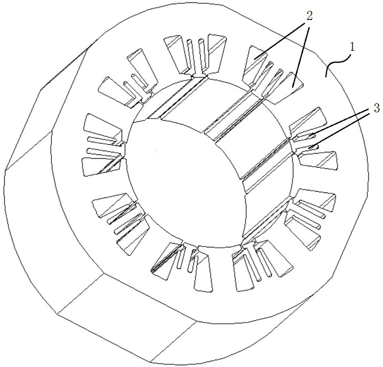
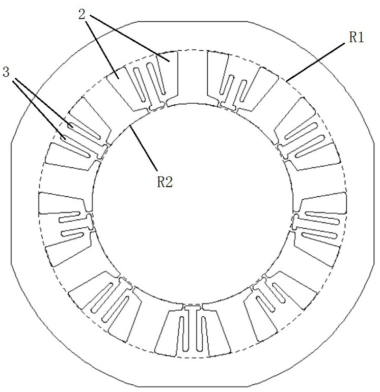
[0031] Such as Figure 1-2 As shown in , this embodiment provides a stator 1 that is provided with two magnetic isolation cavities 3 between two adjacent stator slots 2 . The magnetic isolation cavity 3 axially penetrates the two end faces of the stator 1 on the stator 1 . The magnetic isolation chamber 3 is arranged between two adjacent stator slots 2, close to the excitation winding, and two magnetic isolation chambers 3 are distributed on both sides of the magnetic pole centerline of the two adjacent stator slots 2, thereby hindering the leakage flux. produce. The magnetic isolation cavity 3 communicates with the adjacent stator slot 2 to form a through slot, which is equivalent to forming a relatively large magnetic resistance and hindering the formation of magnetic flux leakage lines.
[0032] In this embodiment, the structures of the magnetic isolation cavities 3 on the stator 1 are uniform, and the cross-section of the magnetic isolation cavity 3 is a rectangle with r...
Embodiment 2
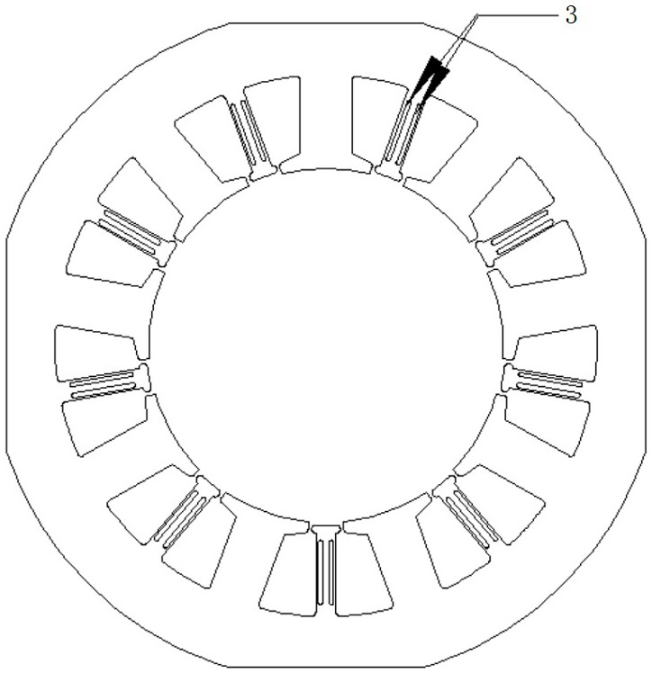
[0035] Such as image 3 As shown in , this embodiment provides a stator 1 that is provided with two magnetic isolation cavities 3 between two adjacent stator slots 2 . The magnetic isolation cavity 3 axially penetrates the two end faces of the stator 1 on the stator 1 . The magnetic isolation chamber 3 is arranged between two adjacent stator slots 2, close to the excitation winding, and two magnetic isolation chambers 3 are distributed on both sides of the magnetic pole centerline of the two adjacent stator slots 2, thereby hindering the leakage flux. produce. There is no communication between the magnetic isolation cavity 3 and the adjacent stator slot 2, so as to prevent the excessive motor reluctance torque from causing high requirements on the mechanical strength of the motor.
[0036] In this embodiment, the structures of the magnetic isolation cavities 3 on the stator 1 are uniform, and the cross section of the magnetic isolation cavity 3 is rectangular.
Embodiment 3
[0038] Such as Figure 4 As shown in , this embodiment provides a stator 1 that is provided with two magnetic isolation cavities 3 between two adjacent stator slots 2 . The magnetic isolation cavity 3 axially penetrates the two end faces of the stator 1 on the stator 1 . Two magnetic isolation cavities 3 are arranged between two adjacent stator slots 2, close to the field winding. The cross sections of the two magnetic isolation cavities 3 are oval, but the widths of the two magnetic isolation cavities 3 are different. The two magnetic isolation cavities 3 are arranged along the pole centerlines of the two adjacent stator slots 2, so as to prevent the generation of magnetic leakage flux. The two magnetic isolation cavities 3 are not connected to the stator slot 2, so as to prevent the excessive motor reluctance torque from causing higher mechanical strength requirements of the motor.
PUM
 Abstract
Description
Claims
Application Information
 - R&D Engineer
- R&D Manager
- IP Professional
- Industry Leading Data Capabilities
- Powerful AI technology
- Patent DNA Extraction
Browse by: Latest US Patents, China's latest patents, Technical Efficacy Thesaurus, Application Domain, Technology Topic, Popular Technical Reports.
© 2024 PatSnap. All rights reserved.Legal|Privacy policy|Modern Slavery Act Transparency Statement|Sitemap|About US| Contact US: help@patsnap.com


