Textile equipment with driving mechanism and textile equipment transformation method

A technology of driving mechanism and textile equipment, applied in the direction of textile and paper making, weaving, and processing textile material drums, etc., can solve the problems of inconvenient operation and cumbersome manual operation of users, improve processing quality, ensure transmission stability and Efficiency and improved usability

Active Publication Date: 2021-02-12
MINJIANG UNIV
View PDF6 Cites 0 Cited by
  • Summary
  • Abstract
  • Description
  • Claims
  • Application Information

AI Technical Summary

Problems solved by technology

[0006] The object of the present invention is to provide a textile equipment with a driving mechanism and a method for renovating the textile equipment, so as to solve the problem in the above-mentioned background technology that it is impossible to collect the formed materials through the preset driving structure, and allow the user to conveniently check the single group. The rapid replacement and unloading of materials requires cumbersome manual operations by the user, which brings inconvenience to the user's operation. To realize the processing work of automatic unloading outwards, the user needs to go deep into the inside of the device for processing

Method used


Image

  • Textile equipment with driving mechanism and textile equipment transformation method
  • Textile equipment with driving mechanism and textile equipment transformation method
  • Textile equipment with driving mechanism and textile equipment transformation method

Examples


Embodiment Construction

[0031] The following will clearly and completely describe the technical solutions in the embodiments of the present invention with reference to the accompanying drawings in the embodiments of the present invention. Obviously, the described embodiments are only some, not all, embodiments of the present invention. Based on the embodiments of the present invention, all other embodiments obtained by persons of ordinary skill in the art without making creative efforts belong to the protection scope of the present invention.

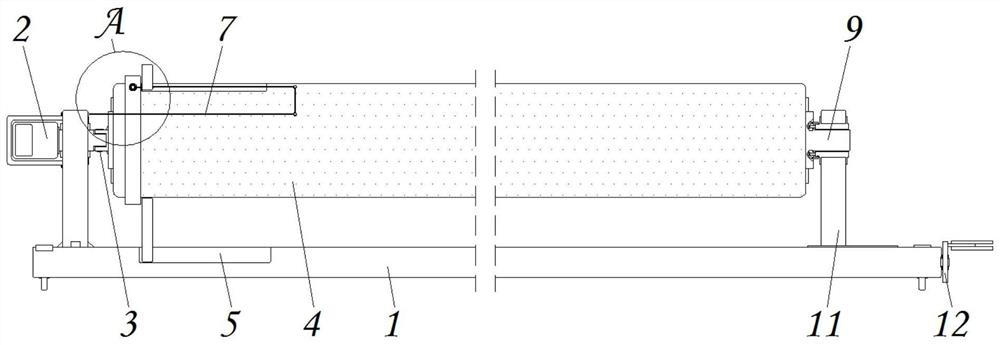
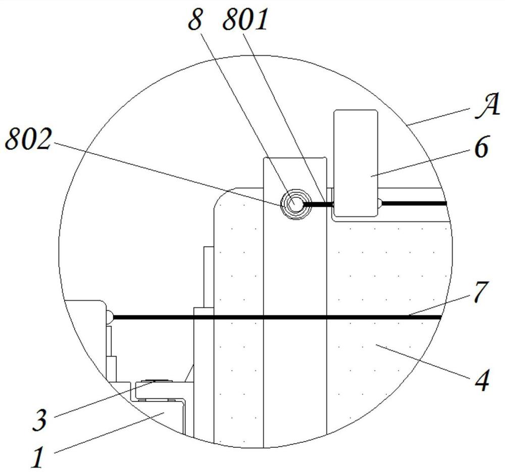
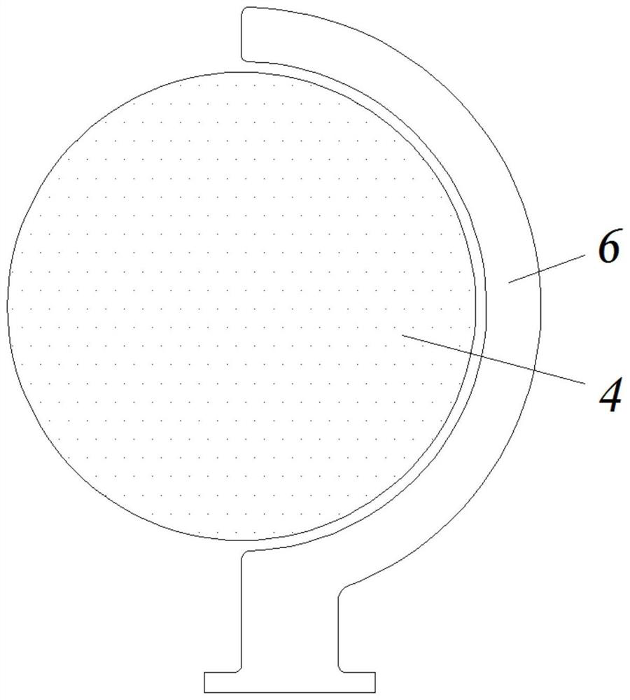
[0032] see Figure 1-6, the present invention provides a technical solution: textile equipment with a driving mechanism and a textile equipment transformation method, including a mounting seat 1, a driving motor 2, a movable shaft 3, a winding roller 4, a first chute 5, a docking member 6, a first Pull cord 7, connecting shaft 8, nesting part 9, second chute 10, limiter 11, mounting disc 12, threaded rod 13, mounting bearing 14, connecting part 15, rotating sh...


PUM


Abstract

The invention discloses textile equipment with a driving mechanism and a textile equipment transformation method. The textile equipment comprises a mounting base, a driving motor, a movable shaft, a limiting piece and an abutting piece, the driving motor is mounted at the outer end of the mounting base through bolts, the movable shaft is mounted at the upper end of the mounting base in a penetrating mode, a winding roller is fixedly connected to the outer side of the movable shaft, the winding roller is connected with the upper end of the mounting base, a first sliding groove is formed in theupper end face of the mounting base, and a butt joint piece is mounted on the outer side of the first sliding groove in a nested mode. According to the textile equipment with the driving mechanism andthe textile equipment transformation method, after the winding roller is separated from the limiting state, a user can push the winding roller to rotate outwards through the movable shaft, and meanwhile, a stressed pull rope is wound along with the winding roller to drive a connected arc-shaped butt joint piece to move outwards along the outer surface of the winding roller in an attached mode, thus contacted winding materials are pushed outwards, and the working effect of automatic discharging is stably and conveniently achieved along the outer side of the winding roller.

Description

technical field [0001] The invention relates to the technical field of textile equipment, in particular to textile equipment with a driving mechanism and a method for transforming the textile equipment. Background technique [0002] With the continuous improvement of people's living standards, people's demand for clothing is gradually increasing, and no matter what kind of clothing is made of different textile fabrics, most of the textile fabrics need to be spun and weaved during the production process. And dyeing and other steps, and no matter what kind of step in the end, it is necessary to collect the formed cloth produced by it through the winding structure, but there are still certain defects in the existing textile equipment, such as: [0003] 1. The existing textile equipment cannot allow the user to quickly replace and unload a single group of materials after collecting the formed materials through the preset driving structure, which requires cumbersome manual operat...

Claims


Application Information

Patent Timeline
Patent Type & Authority Applications(China)
IPC IPC(8): D03D49/20D04B15/88D04B27/34D06B23/02
CPCD03D49/20D04B15/88D04B27/34D06B23/02
Inventor 卢麒麟卢琳娜
Owner MINJIANG UNIV
Why Eureka
Try Eureka