Environmentally friendly bearing plastic cage production line
A cage and environment-friendly technology, applied in the direction of instruments, sounding equipment, etc., can solve the problems affecting the production environment of the workshop, affecting the physical and mental health of workers, and noise pollution, so as to improve the quality of the production environment, reduce noise pollution, and reduce noise. The effect of the spread
- Summary
- Abstract
- Description
- Claims
- Application Information
AI Technical Summary
Problems solved by technology
Method used
Image
Examples
Embodiment 1
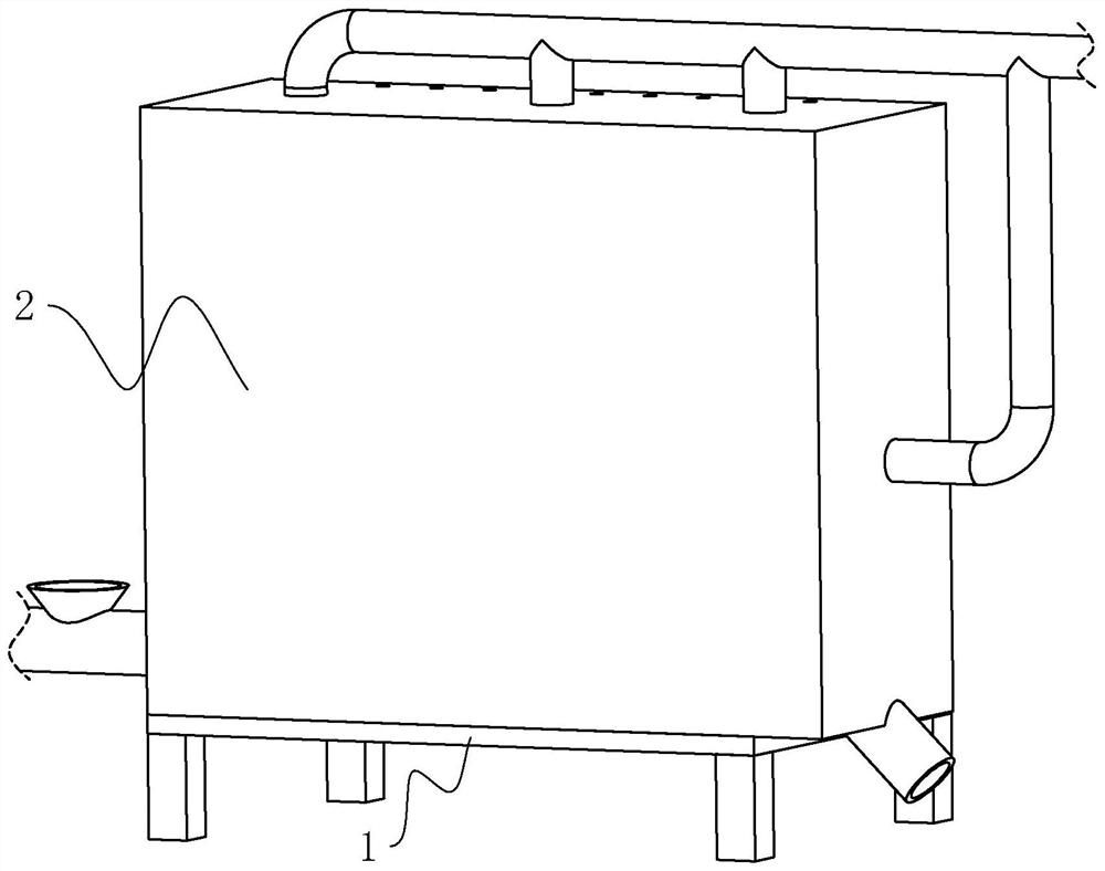
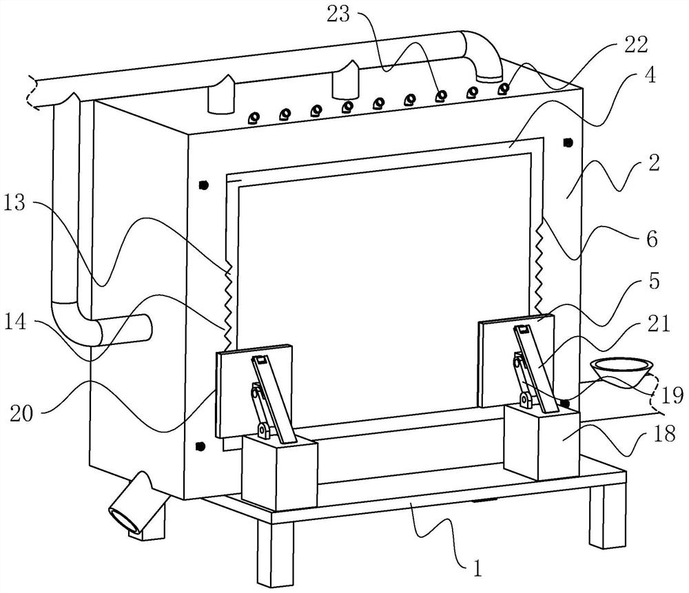
[0038] refer to figure 2 , The production line of environmentally friendly bearing plastic cages includes a frame 1 and a chassis 2 set on the frame 1 . Wherein, the side wall of the cabinet 2 is provided with a sound insulation board 4 for reducing noise transmission, and the frame 1 is provided with an extruding plate 5 for squeezing the side wall of the cabinet 2 and the sound insulation board 4 .
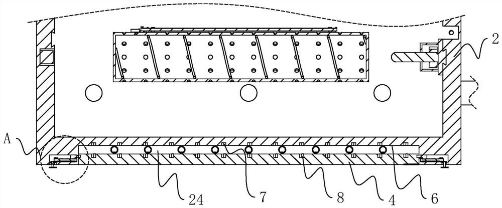
[0039] refer to image 3 , Offer groove 6 on the outer side wall of cabinet 2, the inner chamber of groove 6 is rectangular parallelepiped setting, offer a plurality of honeycomb grooves 2 7 on the inner wall of groove 6. The sound insulation board 4 is arranged in a rectangular shape, and the sound insulation board 4 is detachably connected to the side wall of the chassis 2 and can cover the notch of the groove 6 .
[0040] refer to image 3 , One side of the sound insulation board 4 is provided with a number of honeycomb grooves 8, and the cabinet 2 is provided with a fixi...
Embodiment 2
[0056] refer to Figure 6 , an environment-friendly bearing plastic cage production line, the difference from Embodiment 1 is that the fixing device includes a fixing plate 98 fixedly connected to the inner wall of the groove 6, a fixing rod 99 fixedly connected to the fixing plate 98, and a soundproof The positioning hole 910 used for the insertion of the fixed rod 99 on the plate 4, the iron block 911 embedded on the body of the fixed rod 99, and the magnetic block 912 fixedly connected to the inner wall of the positioning hole 910 to cooperate with the iron block 911 to absorb.
[0057] Wherein, the fixing plate 98 is arranged in a square ring shape and is arranged along a direction parallel to the plane where the notch of the groove 6 is located.
[0058] refer to Figure 6 , the fixing rod 99 is arranged in a cylindrical shape and arranged along a direction perpendicular to the surface of the fixing plate 98 , and the cavity of the positioning hole 910 is arranged along ...
PUM
 Abstract
Description
Claims
Application Information
 - R&D Engineer
- R&D Manager
- IP Professional
- Industry Leading Data Capabilities
- Powerful AI technology
- Patent DNA Extraction
Browse by: Latest US Patents, China's latest patents, Technical Efficacy Thesaurus, Application Domain, Technology Topic, Popular Technical Reports.
© 2024 PatSnap. All rights reserved.Legal|Privacy policy|Modern Slavery Act Transparency Statement|Sitemap|About US| Contact US: help@patsnap.com


