Fuel injector

A technology for fuel injectors and valve components, applied in fuel injection devices, special fuel injection devices, charging systems, etc., can solve problems such as the inconstant closing time of control valves, and achieve the effect of improving the accuracy of injection volume and enhancing swirl flow

Active Publication Date: 2021-02-09
ROBERT BOSCH GMBH
View PDF7 Cites 0 Cited by
  • Summary
  • Abstract
  • Description
  • Claims
  • Application Information

AI Technical Summary

Problems solved by technology

In tests it has been found that, especially at moderate rail or system pressures (here, for example, pressures of approximately 1200 bar), the closing duration of the control valve is not constant due to flow-related effects

Method used


Image

  • Fuel injector
  • Fuel injector
  • Fuel injector

Examples


Embodiment Construction

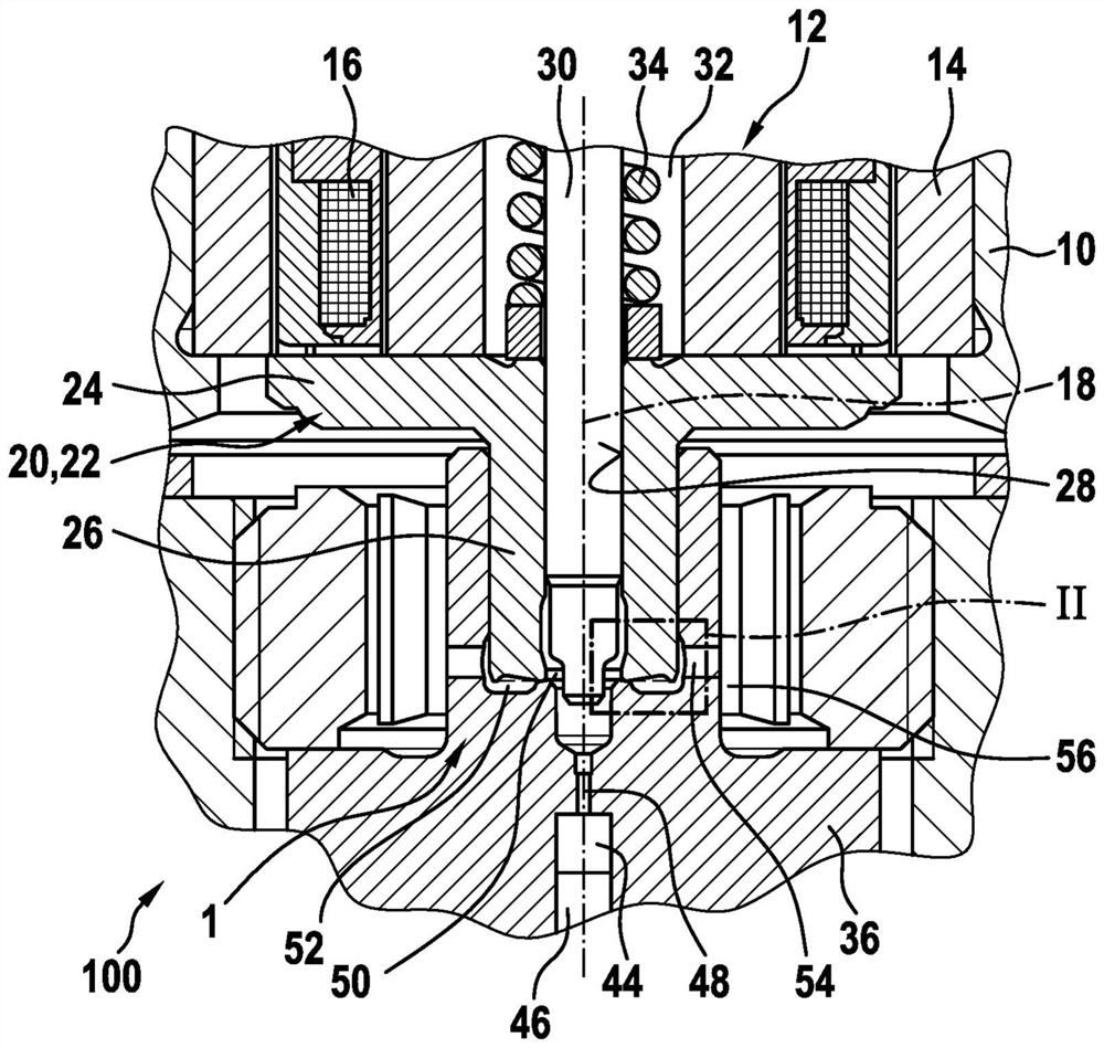
[0024] exist figure 1 The fuel injector 100 shown partially in the center is used to inject fuel into a not shown combustion chamber of a self-igniting internal combustion engine, wherein the system pressure of the fuel stored in the rail can preferably be greater than 2000 bar.

[0025] The fuel injector 100 has an injector housing 10 in which an electromagnet 12 is arranged in a stationary manner. The fuel injector 12 has a magnetic core 14 in which an annular magnetic coil 16 is arranged. When the solenoid coil 16 is energized, a magnetic field is created which attracts the magnetic armature 20 capable of reciprocating on the longitudinal axis 18 and at the same time serves as the valve element 22 and moves it towards the magnetic core 14 until at least indirectly at the core. In the schematic diagram of the drawing, the magnetic armature 20 is shown in a correspondingly de-energized position of the magnetic coil 16 .

[0026] In the exemplary embodiment, the one-piece a...


PUM


Abstract

The invention relates to a fuel injector (100) having a control valve (1; 1a), which is arranged in a housing (10) and can be actuated by an electromagnet (12), for controlling the flow of a pressuremedium from a control chamber (44) into a low-pressure chamber (56), wherein the control valve (1; 1a) has a valve element (22; 22a), which can be moved by the electromagnet (12) in the direction of alongitudinal axis (18), wherein a valve chamber (50) connected to the control chamber (44) adjoins the valve element (22; 22a) and the valve element (22a; 22a) interacts with a seat face (40) formedon a valve body (36; 36a) in order to open and close a terminating connection (52) connecting the valve chamber (50) and the low-pressure chamber (56), and wherein an end face (62) of the valve element (22; 22a) has first ring-groove-shaped recess (63; 63a) and the valve piece (36; 36a) has a second ring-groove-shaped recess (64).

Description

technical field [0001] The invention relates to a fuel injector according to the features of the preamble of claim 1 . Background technique [0002] A fuel injector according to this generic is known from DE 10 2012 220 031 A1 of the applicant. The geometric structure constructed in the area between the valve element and the valve body of the control valve of the fuel injector has two annular groove-shaped recesses, which when the valve element is opened serve to allow fuel to flow from the control chamber to the low pressure of the fuel injector In the region, fuel flows through the depression. [0003] In such fuel injectors, by a suitable choice of the geometry of the valve element and of the valve part, especially during the duration of the actuation, the fuel injector should be realized even at different system pressures or pressures in the control chamber. uniform opening behavior or closing behavior. In tests it has been found that, especially at moderate rail or s...

Claims


Application Information

Patent Timeline
Patent Type & Authority Applications(China)
IPC IPC(8): F02M63/00F02M47/02
CPCF02M47/027F02M63/0015F02M63/0021F02M63/0031F02M63/0077F02M63/0078F02M63/008F02M2200/306Y02T10/40
Inventor O·蒂克尔M·赫雷拉P·瓦赫特L·奥勒姆斯F·菲舍尔D·菲舍尔
Owner ROBERT BOSCH GMBH
Why Eureka
Try Eureka