LED display screen capable of being controlled by wireless remote network
A technology of LED display screen and remote network, applied in the field of display screen, can solve the problems of inconvenient maintenance and replacement, cumbersome LED display screen splicing operation, etc., to achieve the effect of prolonging the service life, facilitating the transfer operation, and avoiding the waste of resources
- Summary
- Abstract
- Description
- Claims
- Application Information
AI Technical Summary
Problems solved by technology
Method used
Image
Examples
Embodiment 1
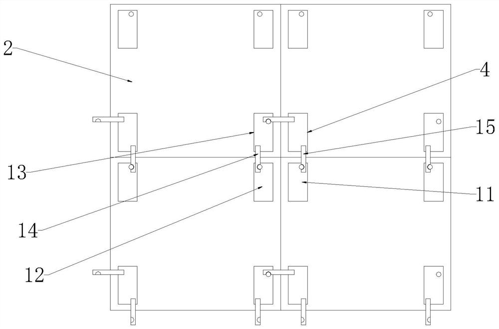
[0030] refer to image 3 , an LED display screen capable of wireless remote network control, comprising a display screen body 1 and a mounting frame 2, the display screen body 1 is mounted on the front of the mounting frame 2, and first positioning boxes are respectively fixedly installed at the four corners of the back of the mounting frame 2 4. The second positioning box 11, the third positioning box 12 and the fourth positioning box 13, and the overall structure of the four display screen bodies 1 and the installation frame 2 are spliced to form a fixed display splicing piece, and the first positioning box 4 is far away from One side of the mounting frame 2 is rotatably equipped with two second hanging boards 15 having the same structure, and the fourth positioning box 13 is rotatably equipped with the first hanging board 14, the second positioning box 11, the third positioning box 12 and the fourth positioning box 13. The side of the positioning box 13 away from the moun...
Embodiment 2
[0033] refer to Figure 4-8, in this embodiment, a positioning assembly 17 is installed between the four adjacent mounting frames 2 to be spliced, and the positioning assembly 17 includes a vertical plate 171, a transverse plate 172, a chute 173, a slider 174, and a threaded rod 175 , Positioning splint 176, driving tooth plate 177, driven tooth plate 178, tooth plate groove 179, adjustment rod 1710, movable plate 1711, card 1712, limit groove 1713 and return spring 1714, vertical plate 171 intersects with transverse plate 172 Form a cross shape, and two groups of chute 173 that are symmetrically distributed are arranged on the transverse plate 172. A slider 174 is slidably installed inside the chute 173, and the top and bottom ends of the slider 174 are fixedly connected with a positioning splint 176 for positioning. The splint 176 extends to the outside of the transverse plate 172 .
[0034] The interior of the intersection of the transverse plate 172 and the vertical plate...
Embodiment 3
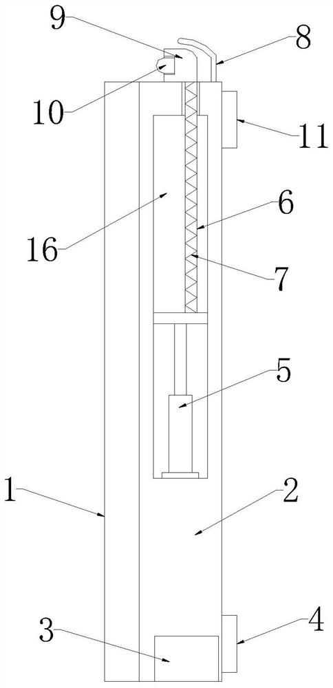
[0039] refer to Figure 1-2 and Figure 9 , in this embodiment, the interior of the installation frame 2 is provided with an installation groove 16, and the bottom inner wall of the installation groove 16 is fixedly installed with an electric telescopic rod 5, and the end of the electric telescopic rod 5 is fixedly connected with two symmetrically distributed elastic rods. Rubber rods 6, and the ends of the two elastic rubber rods 6 extend to the top of the installation frame 2 and are fixedly connected with a mounting plate 9, the front of the mounting plate 9 is equipped with a supplementary light 10, and between the two elastic rubber rods 6 A rain cloth 7 is installed, and a solar panel 8 is fixedly connected to the top of the installation frame 2 .
[0040] The solar panel 8 is arranged in an arc shape, and the mounting plate 9 is provided with a chamfer near the side of the solar panel 8, and the mounting plate 9 is in sliding contact with the solar panel 8, and the bot...
PUM
 Abstract
Description
Claims
Application Information
 - R&D
- Intellectual Property
- Life Sciences
- Materials
- Tech Scout
- Unparalleled Data Quality
- Higher Quality Content
- 60% Fewer Hallucinations
Browse by: Latest US Patents, China's latest patents, Technical Efficacy Thesaurus, Application Domain, Technology Topic, Popular Technical Reports.
© 2025 PatSnap. All rights reserved.Legal|Privacy policy|Modern Slavery Act Transparency Statement|Sitemap|About US| Contact US: help@patsnap.com


