Change detection method based on plurality of controllable pyramids

A change detection and pyramid technology, applied in the fields of artificial intelligence and computer vision, it can solve the problems of inapplicability of small change detection, and achieve the effect of solving geometric inconsistencies and lighting inconsistencies

Active Publication Date: 2021-02-09
TIANJIN UNIV
View PDF6 Cites 1 Cited by
  • Summary
  • Abstract
  • Description
  • Claims
  • Application Information

AI Technical Summary

Problems solved by technology

Traditional methods use background modeling methods for change detection [3]. The goal of these methods is to detect significant changes in the scene and exclude insignificant changes, but these methods are not applicable to small change detection

Method used


Image

  • Change detection method based on plurality of controllable pyramids
  • Change detection method based on plurality of controllable pyramids
  • Change detection method based on plurality of controllable pyramids

Examples


Embodiment Construction

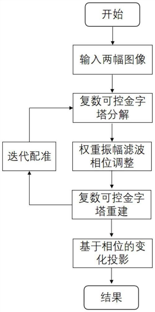
[0032] (1) Image registration based on complex controllable pyramid

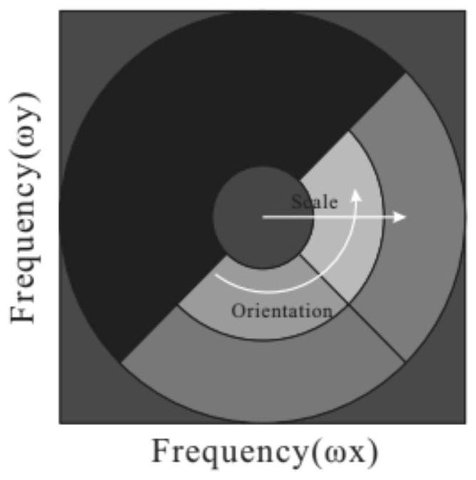
[0033] Complex steerable pyramid (Complex steerable pyramid)[4][5] is a frequency-domain transformation method that can decompose an image into time-frequency domains of different scales and directions.

[0034] Two images of the same scene taken at different times (I pre , I cur ) there is a difference in position, the two images are decomposed into sub-bands of different direction scales through a complex controllable pyramid, and the phase is adjusted for registration. Specific steps are as follows:

[0035] (4) The image is decomposed into subbands of different direction scales through a complex controllable pyramid, and each subband contains two components, amplitude A and phase Φ.

[0036] Decompose the image I into subbands S of different scales and orientations ω,θ ,,

[0037]

[0038] I represents the input image, ω and θ are the indices of different filters, ω represents the scale, and θ re...


PUM


Abstract

The invention relates to a change detection method based on a plurality of controllable pyramids, which is used for carrying out change detection on the difference between two images (Ipre and Icur) of the same scene shot at different moments, and comprises the following steps: decomposing the two images (Ipre and Icur) into sub-bands with different direction scales through the plurality of controllable pyramids, wherein each sub-band comprises two component amplitudes A and a phase phi; performing image registration by adjusting the phase difference between different sub-bands of the two images; reconstructing the different sub-bands after phase adjustment to obtain a final registered image; analyzing the change of the phase to obtain the real change of the scene.

Description

technical field [0001] The invention belongs to the fields of computer vision and artificial intelligence, and relates to a small change detection method based on complex controllable pyramids. Background technique [0002] The technical background that the present invention relates to has: [0003] (1) Image alignment: There are differences in the corresponding positions of the two images taken at different times, so image alignment is crucial for subsequent change detection. Optical flow estimation is a field closely related to image alignment. The optical flow method obtains a dense displacement vector field describing the displacement between two images. The traditional method solves an optimization problem through the variational method. The pioneer work of the optical flow method was proposed by Horn and Schunck [1], and the variational method quickly dominated the field of optical flow estimation. Afterwards, related expansion work can solve large displacement probl...

Claims


Application Information

Patent Timeline
Patent Type & Authority Applications(China)
IPC IPC(8): G06T7/00G06T7/30
CPCG06T7/001G06T7/30G06T2207/20016
Inventor 万亮冯伟王旭之张乾
Owner TIANJIN UNIV
Why Eureka
Try Eureka