Chip recovery device for machine tool machining

A technology for recycling devices and chips, applied in metal processing equipment, metal processing machinery parts, manufacturing tools, etc., can solve the problems affecting recycling and chip corrosion, etc.

Inactive Publication Date: 2021-02-09
王军
View PDF0 Cites 3 Cited by
  • Summary
  • Abstract
  • Description
  • Claims
  • Application Information

AI Technical Summary

Problems solved by technology

[0002] When the machine tool is cutting mechanical parts, it will produce a lot of cutting iron chips, which will be mixed in the coolant. In order to recycle these chips, they need to be separated from the coolant. At presen...

Method used


Image

  • Chip recovery device for machine tool machining
  • Chip recovery device for machine tool machining
  • Chip recovery device for machine tool machining

Examples


Embodiment 1

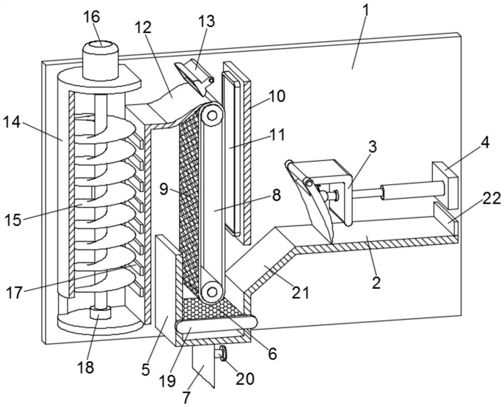
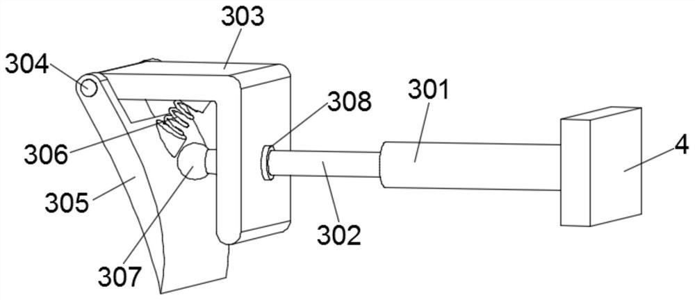
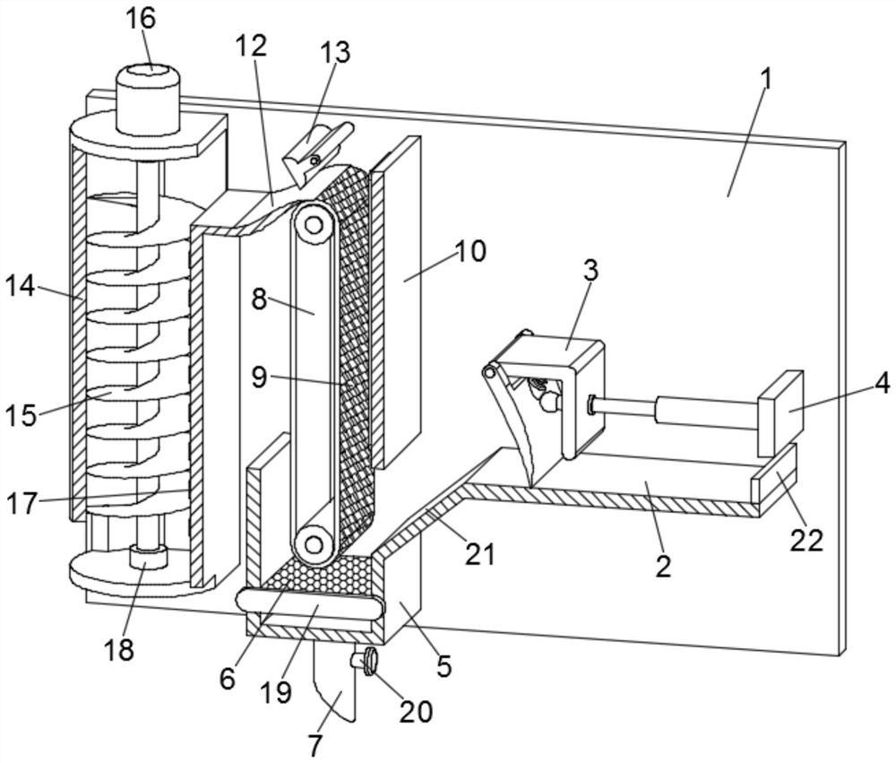
[0024] see Figure 1-2 , a chip recovery device for machine tool processing, comprising a backboard 1 and a platform 2, a pusher mechanism 3 is arranged above the platform 2, and the pusher mechanism 3 is installed on the backboard 1 through a mounting plate 4, and the pusher The material mechanism 3 includes a fixed sleeve 301, a telescopic column 302, a bracket 303 and a push plate 305. The fixed sleeve 301 is fixedly installed on the end surface of one side of the mounting plate 4, and the movable sleeve of the fixed sleeve 3 is provided with a telescopic column. 302, the top ball 307 is fixed at the end of the telescopic column 302, and a bracket 303 is movable on the telescopic column 302. The end of the bracket 303 away from the telescopic column 302 is rotated by a rotating shaft 304 and a push plate 305 is installed. Both sides of the plate 305 are against the back plate 1, and a return spring 306 is connected between the push plate 305 and the bracket 303;

[0025] W...

Embodiment 2

[0038] In order to facilitate the cleaning and replacement of the filter screen 6, this embodiment has made further improvements on the basis of Embodiment 1. The improvement is: the horizontal movable card of the filter screen 6 is set in the chip collection groove 5, and the filter screen 6 The extension end is provided with a push-pull plate 19, through which the filter screen 6 can be easily inserted into the chip collection groove 5 or extracted from the chip collection groove 5, thereby facilitating the cleaning and replacement of the filter screen 6 and improving maintenance efficiency.

[0039] The chip recovery device for machine tool processing first pushes the chips and coolant on the platform 2 into the chip collection groove 5 through the pushing mechanism 3. When the pushing plate 305 in the pushing mechanism 3 advances, it contacts with the surface of the platform 2 to ensure that the chips The cleaning is thorough. When the push plate 305 returns, it will be sep...


PUM


Abstract

The invention discloses a chip recovery device for machine tool machining. The chip recovery device comprises a back plate and a platform, wherein a material pushing mechanism is arranged above the platform; a chip collecting groove is formed in one end of the platform, a filter screen is installed in the chip collecting groove, a conveying belt is arranged above the chip collecting groove, an electromagnet is laid on the conveying belt, a partition plate is arranged between the conveying belt and the material pushing mechanism, and a dehumidifier is installed on the partition plate; and a scraping plate is arranged at the upper end of the conveying belt, an air blower is arranged above the scraping plate, a shell is arranged at the end, far away from the partition plate, of the scraping plate, a spiral blade is rotationally installed in the shell, and a plurality of drying plates are vertically arranged on the inner wall of the shell. According to the chip recovery device for machinetool machining, chips are pushed into the chip collecting groove through the material pushing mechanism, then iron chips are adsorbed through the electromagnet on the conveying belt, and dehumidification treatment is carried out on the iron chips through the dehumidifier; and the chips on the conveying belt are scraped off through the scraping plate at the upper end, the chips are blown into the shell through the air blower, water on the surfaces of the chips is removed again through the drying plates, so that the chips are prevented from being rusted, and the recovery quality is guaranteed.

Description

technical field [0001] The invention relates to the technical field of mechanical processing, in particular to a chip recycling device for machine tool processing. Background technique [0002] When the machine tool is cutting mechanical parts, it will produce a lot of cutting iron chips, which will be mixed in the coolant. In order to recycle these chips, they need to be separated from the coolant. At present, most of them are filtered. The net separates the chips from the coolant, and a large amount of coolant still adheres to the surface of the separated chips, which easily leads to chip corrosion and affects recycling and reuse. Contents of the invention [0003] The object of the present invention is to provide a chip recovery device for machine tool processing, so as to solve the problems raised in the above-mentioned background technology. [0004] To achieve the above object, the present invention provides the following technical solutions: [0005] A chip recove...

Claims


Application Information

Patent Timeline
IPC IPC(8): B23Q11/00B01D29/80B01D29/94B01D29/84
CPCB01D29/80B01D29/84B01D29/94B23Q11/005B23Q11/0064
Inventor 王军
Owner 王军
Why Eureka
Try Eureka