Defogging device and camera module with same

A technology of a defogging device and a camera module, applied in the optical field, can solve the problems of poor defogging effect of the camera module, etc., and achieve the effect of firm and reliable connection position, fast and effective defogging effect, and compact structure.

Pending Publication Date: 2021-02-05
ZHEJIANG SUNNY SMARTLEAD TECH CO LTD
View PDF0 Cites 0 Cited by
  • Summary
  • Abstract
  • Description
  • Claims
  • Application Information

AI Technical Summary

Problems solved by technology

[0003] The purpose of the present invention is to provide a defogging device and a camera module with the device, so as to solve the problem of poor defogging effect of the camera module

Method used


Image

  • Defogging device and camera module with same
  • Defogging device and camera module with same
  • Defogging device and camera module with same

Examples


Embodiment approach

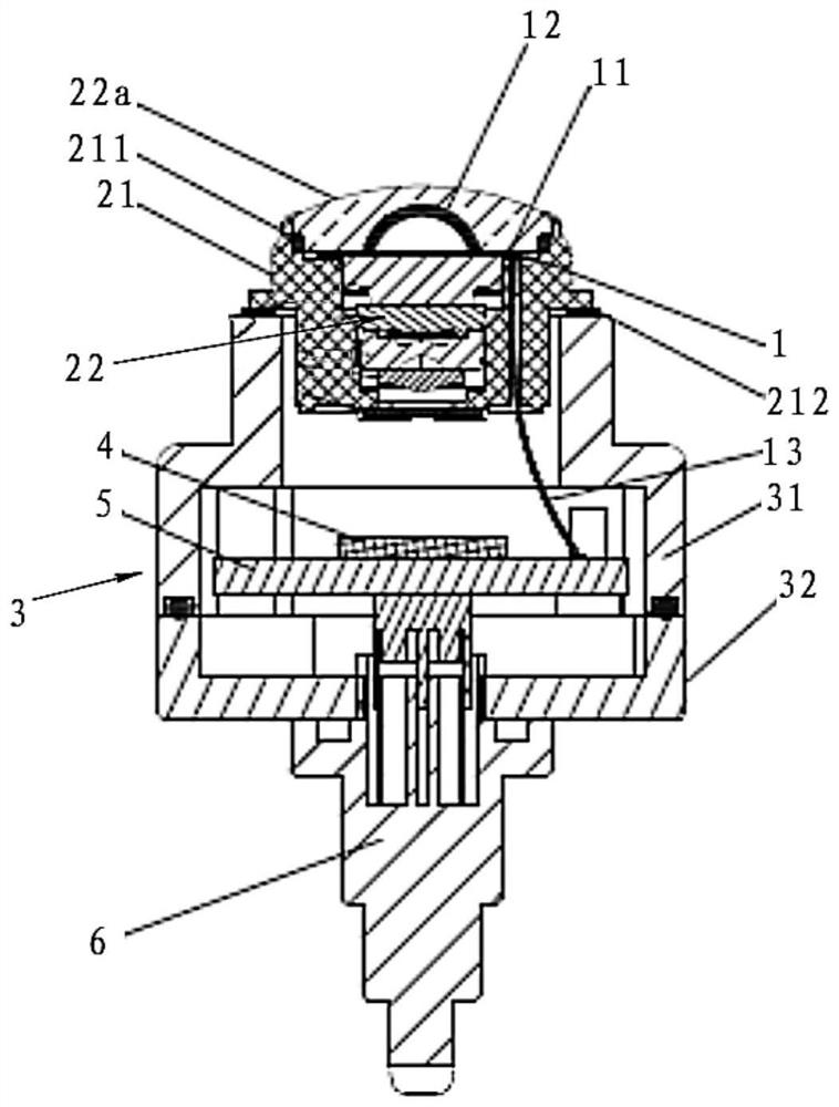
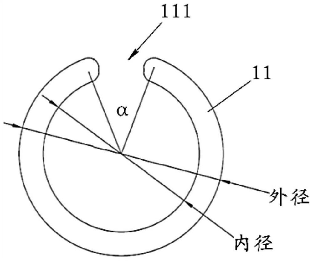
[0038] combine figure 1 with figure 2 As shown, according to an embodiment of the present invention, a defogging device of the present invention includes: a planar heating part 11 in the shape of a planar ring, a curved heating part 12 in the shape of a curved surface, and a conductive connection structure 13 . In this embodiment, the planar heating part 11 is arranged around the curved heating part 12 , and the inner ring edge of the planar heating part 11 is connected to the outer edge of the curved heating part 12 . In this embodiment, the planar heating part 11 and the curved surface heating part 12 are controlled as a whole to achieve synchronous heating effects. In this embodiment, the flat heating part 11 and the curved heating part 12 are connected by coating

[0039] Through the above setting, by adopting the combined heating method of the curved surface heating part in the middle position and the outer heating part in the ring edge, the defogging device of the pre...


PUM


Abstract

The invention relates to a defogging device and a camera module with the defogging device, and the defogging device comprises a plane heating part (11) in a plane circular ring shape, a curved surfaceheating part (12) in a curved surface shape, and a conductive connection structure (13). The plane heating part (11) is arranged around the curved surface heating part (12), and the inner ring edge of the plane heating part (11) is connected with the outer edge of the curved surface heating part (12). The defogging device is compact in structure, wider in application range and better in reliability.

Description

technical field [0001] The invention relates to the field of optics, in particular to a defogging device and a camera module with the device. Background technique [0002] With the application of intelligence and unmanned driving, the vehicle camera module, as the visual system of the car, is more and more used in the car, which greatly improves the convenience of the driver. In order to face various driving environments, the requirements for on-board camera modules are getting higher and higher. Among them, in some specific environments, such as severe cold regions, after the car starts to drive, the camera outside the cabin can easily generate water mist on the lens surface, which seriously affects driving safety. The existing vehicle-mounted camera modules add corresponding heating structures to eliminate the water mist generated in the lens, but these heating structures have the disadvantages of being large in size, affecting the imaging field of view of the lens, or ha...

Claims


Application Information

Patent Timeline
Patent Type & Authority Applications(China)
IPC IPC(8): H04N5/225B60R11/04G03B17/55
CPCB60R11/04G03B17/55H04N23/50H04N23/55H04N23/57H04N23/51
Inventor 张扣文许毅解伟丁志
Owner ZHEJIANG SUNNY SMARTLEAD TECH CO LTD
Why Eureka
Try Eureka