Full-automatic hanging scaffold mechanism

A fully automatic, hanging tray technology, applied in thin material handling, conveying filamentous materials, transportation and packaging, etc., can solve the problems of large space, easy to scratch the surface of the wrapped wire, complex structure, etc.

Pending Publication Date: 2021-02-05
WUXI JUYI TONGCHUANG TECH CO LTD
View PDF12 Cites 0 Cited by
  • Summary
  • Abstract
  • Description
  • Claims
  • Application Information

AI Technical Summary

Problems solved by technology

Some defects were found after use: First, before winding the empty reel, the end of the thread is usually fixed in the wire catcher before winding, then the end of the thread needs to be disengaged after the reel is full, the current reel transfer manipulator does not It has this automatic operation; secondly, after the thread end slips off, it becomes a free end, which is easy to scratch the surface of the wound thread, and after the thread tail is cut off, it will also become a free end, which will also scratch the surface of the wound thread; The third is that the existing wire reel transfer manipulator grabs from the outside of the wire reel, and the grasp is unstable, which often requires manual correction, which cannot meet the high-speed production requirements, is not conducive to the realization of full automation, and has a complex structure and requires a relatively large space; Fourth, the scope of application of the equipment is small, and the parts of the equipment need to be replaced for plates of different sizes, which is costly

Method used


Image

  • Full-automatic hanging scaffold mechanism
  • Full-automatic hanging scaffold mechanism
  • Full-automatic hanging scaffold mechanism

Examples


Embodiment 1

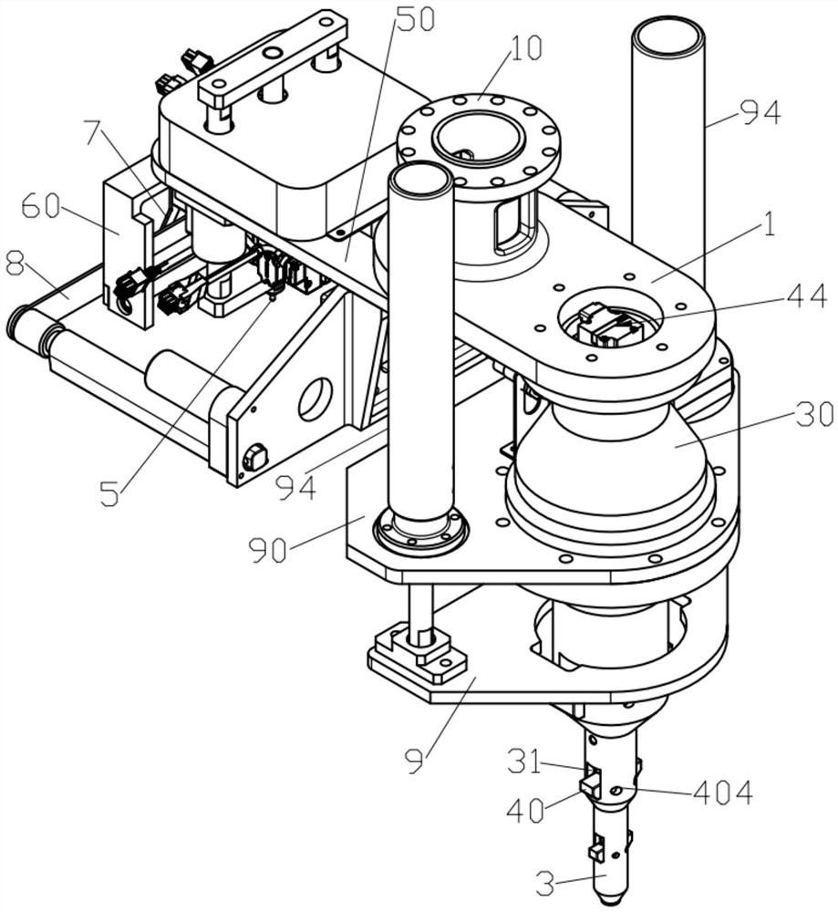
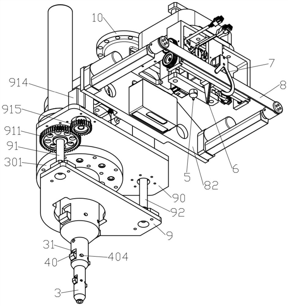
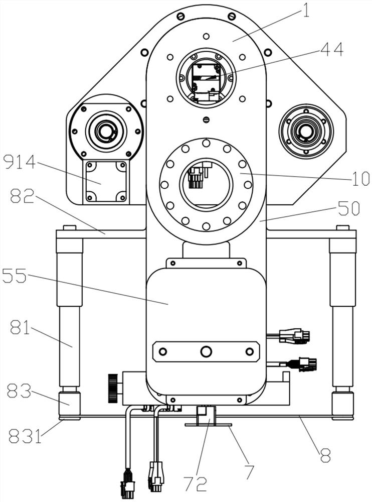
[0049] Such as Figures 1 to 4 As shown, a fully automatic suspension mechanism according to an embodiment of the present invention includes a base 1 , a thread end processing device disposed at one end of the base 1 , and a hoisting device disposed at the other end of the base 1 .

[0050] A manipulator positioning ring 10 is installed on the base 1, and the manipulator positioning ring 10 is used to connect the manipulator, so as to realize the cooperation between the fully automatic suspension mechanism and other equipment parts.

[0051] Such as Figures 5 to 7 As shown, the hoisting device includes a suspension pan shaft 3 , a control shaft 4 and a hinge block assembly 40 . The suspension pan shaft 3 is a hollow structure, the control shaft 4 is located in the suspension pan shaft 3, the hinge block assembly 40 is arranged symmetrically with respect to the control shaft 4, and the hinge block assembly 40 is rotatably connected to the suspension pan shaft 3 through the po...

Embodiment 2

[0071] Such as Figures 21 to 22 As shown, the main difference between the full-automatic suspension mechanism described in Embodiment 2 and Embodiment 1 is that the control shaft driver 44 for driving the control shaft 4, the lifting structure of the driving plate tool pressing plate 9, and the driving off-line top 5 The off-line drivers are different. In this embodiment, pneumatic control is mainly used.

[0072] Such as Figure 22 As shown, the control shaft driver 44 is a cylinder 44B. The cylinder body of the cylinder 44B is installed on the top of the suspension pan shaft 3 . The piston rod of the cylinder 44B is connected to the top of the control shaft 4 . When the cylinder 44B is used as the control shaft driving member 44, the up and down movement of the control shaft 4 relative to the suspension pan shaft 3 is realized through the expansion and contraction of the piston rod of the cylinder 44B. Specifically, when the piston rod of the cylinder 44B stretches out, ...


PUM


Abstract

The invention discloses a full-automatic hanging scaffold mechanism. The full-automatic hanging scaffold mechanism comprises a base, a wire end processing device and a hoisting device, wherein the hoisting device comprises a hanging scaffold shaft, a control shaft and a hinge block component; the hinge block component is rotationally connected to the hanging scaffold shaft through a locating pin;one end of the hinge block component is movably hinged to the control shaft; the control shaft is connected to a control shaft driving part in order to drive the hinge block component to be unfolded or retracted; the upper part of the hanging scaffold shaft is sleeved with a fixing sleeve; the wire end processing device comprises a base plate, a wire disengaging tip, a wire stopping block, a wirehooking part and a wire pressing part; the wire disengaging tip is connected to the base plate in a lifting mode; the wire stopping block is located between the wire disengaging tip and the wire hooking part; the wire stopping block can move left and right relative to the wire disengaging tip; the wire pressing part can stretch out or retract relative to the wire hooking part; and the base plate is connected to the fixing sleeve through the base. According to the full-automatic hanging scaffold mechanism, a wire end is guaranteed to be automatically disengaged, the surface of a wound wire cannot be scratched, the hinge block component is unfolded or retracted in place, a drum is stably hoisted, and automatic transferring of the drum is achieved.

Description

technical field [0001] The invention relates to enameled wire manufacturing equipment, and more specifically relates to a fully automatic hanging pan mechanism. Background technique [0002] The enameled wire is composed of the inner wire and the coating that wraps the wire. During the production process of the enameled wire, the wire needs to be wound on the wire reel by a wire take-up device. After the wire reel is wound, it is necessary to transfer the full reel in time to replace it with an empty reel in time. [0003] At present, some of the switching and transfer of full or empty reels are operated purely manually, and some of them are equipped with a manipulator on the conveying line to grab the wire reel. Some defects were found after use: First, before winding the empty reel, the end of the thread is usually fixed in the wire catcher before winding, then the end of the thread needs to be disengaged after the reel is full, the current reel transfer manipulator does ...

Claims


Application Information

Patent Timeline
IPC IPC(8): B65H67/04B65H67/08
CPCB65H67/0411B65H67/081B65H2701/34
Inventor 梁骁军蔡麟张伟新朗宁卡
Owner WUXI JUYI TONGCHUANG TECH CO LTD
Why Eureka
Try Eureka