Large pipeline continuous splicing structure and splicing method

A pipeline and large-scale technology, applied in the field of continuous splicing structure of large pipelines, can solve the problems of easy misalignment, difficult manual movement, heavy large pipelines, etc., and achieve the effect of preventing misalignment and avoiding the impact of sealing performance

Inactive Publication Date: 2021-02-05
ZHANGJIAGANG HONGCHANG STEEL PLATE CO LTD +1
View PDF8 Cites 0 Cited by
  • Summary
  • Abstract
  • Description
  • Claims
  • Application Information

AI Technical Summary

Problems solved by technology

[0006] The purpose of the present invention is to solve the shortcomings in the prior art that large-scale pipelines are difficult to manually move because they are very bulky, and when docking, they are also prone to misalignment and leakage after connection, and propose a large-scale pipeline Sequential stitching structures and stitching methods

Method used


Image

  • Large pipeline continuous splicing structure and splicing method
  • Large pipeline continuous splicing structure and splicing method
  • Large pipeline continuous splicing structure and splicing method

Examples


Embodiment Construction

[0030] The following will clearly and completely describe the technical solutions in the embodiments of the present invention with reference to the accompanying drawings in the embodiments of the present invention. Obviously, the described embodiments are only some, not all, embodiments of the present invention.

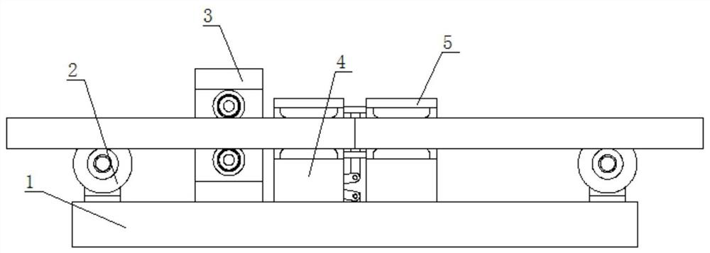
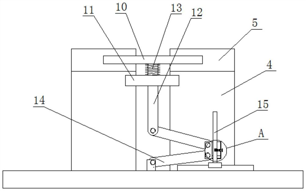
[0031] The invention provides a continuous splicing structure for large pipelines, referring to Figure 1-4 , including a base 1, the top of the base 1 is symmetrically fixed with two support bases 4, and one side of the two support bases 4 is slidably connected to the same fixed rod 10, and one side of the fixed rod 10 is symmetrically fixedly mounted with two pressure plates 5 , and the side where the pressure plate 5 and the support seat 4 are close to each other is clamped with the same pipe, the two pipes are in contact, the top of the base 1 is slidingly connected to the limit rod 15, and the limit rod 15 is slidingly sleeved with a moving ring 16 , the moving ...


PUM


Abstract

The invention belongs to the field of pipeline splicing, particularly relates to a large pipeline continuous splicing structure and a splicing method, and aims to solve the problems that existing large pipelines are difficult to move manually due to the heavy weight, and leakage is easy to occur after connection due to dislocation easily generated during butt joint. According to the technical scheme, the large pipeline continuous splicing structure comprises a base; and two supporting bases are symmetrically and fixedly installed at the top of the base, one sides of the two supporting bases are connected with one same fixing rod in a sliding manner, two pressing plates are symmetrically and fixedly installed at one side of the fixing rod, one same pipeline is clamped at the side, close toeach other, of each pressing plate and the corresponding supporting base, and the two pipelines make contact with each other. According to the large pipeline continuous splicing structure, the two pipelines are spliced, then through limiting rods which are transversely moved, the pipelines can be clamped through the pressing plates, the pipelines are limited, then the pipelines can be convenientlywelded, the problem that the pipelines are dislocated in the butt joint process is effectively solved, and the sealing performance can be further prevented from being affected.

Description

technical field [0001] The invention relates to the technical field of pipe splicing, in particular to a large-scale pipe continuous splicing structure and splicing method. Background technique [0002] Pipe welding is to splice the pipe openings of two pipes together and then use welding to fix them together. [0003] The patent with the notification number CN111473172A discloses a composite spliced ​​pipe, which includes a first pipe body and a second pipe body that is docked and assembled with the first pipe body. The end of the first pipe body opposite to the second pipe body has a movable joint. The first pipe body includes an inner tube and an outer tube. The outer tube is sleeved on the outside of the inner tube, and one end of the inner tube protrudes from the outside of the outer tube. One end face of the outer tube is in contact with one end face of the outer tube, and the other side of the elastic airbag is in contact with the end face of the movable joint. There...

Claims


Application Information

Patent Timeline
Patent Type & Authority Applications(China)
IPC IPC(8): B23K37/053
CPCB23K37/0533
Inventor 毛一标王平许晓璐
Owner ZHANGJIAGANG HONGCHANG STEEL PLATE CO LTD
Why Eureka
Try Eureka