
A plugging welding process

A welding process and hole plugging technology, applied in welding equipment, welding accessories, manufacturing tools, etc., can solve problems such as plugging bolt holes, and achieve the effects of reducing post-weld stress, good control, and easy arc ignition.

Active Publication Date: 2022-05-24
上海宝冶工程技术有限公司 +1
View PDF0 Cites 0 Cited by
  • Summary
  • Abstract
  • Description
  • Claims
  • Application Information

AI Technical Summary

Problems solved by technology

However, there is no effective means in the prior art to completely block the wrongly positioned bolt holes

Method used


Image

  • A plugging welding process
  • A plugging welding process
  • A plugging welding process

Examples


Embodiment Construction

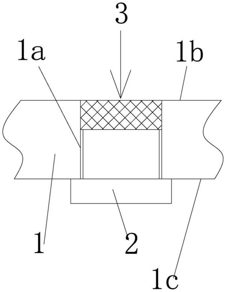
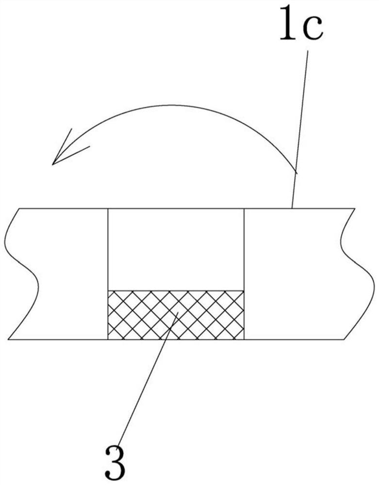
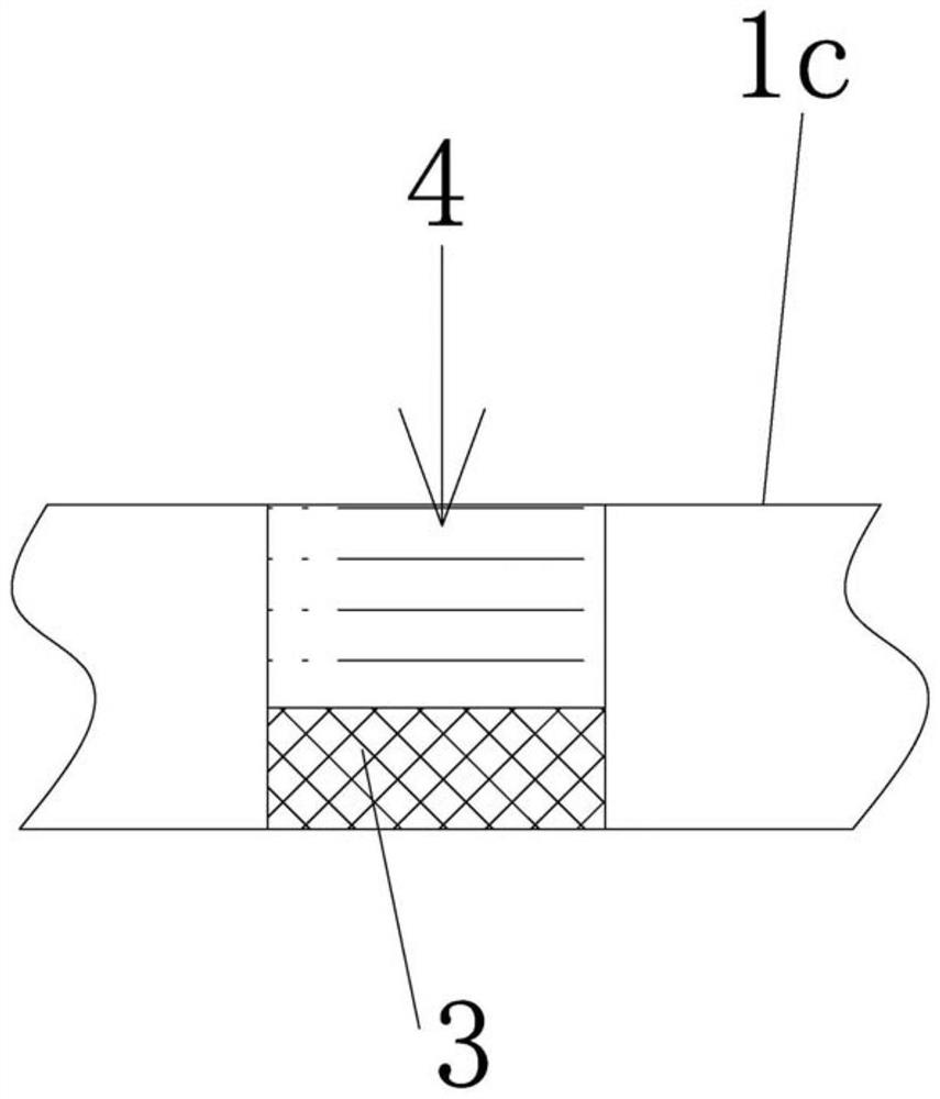
[0029] Attached below Figure 1-3 The present invention is further illustrated with specific examples.

[0030] like figure 1 As shown, a hole plugging welding process includes the following steps:

[0031] S1. Referring to the diameter of the bolt hole 1a at the staggered position, process the tooling block 2 made of conductive metal, so that the diameter of the cylindrical part of the tooling block 2 inserted into the bolt hole 1a is smaller than the diameter of the bolt hole 1a 1-2mm, And make the tooling block 2 have a limit flange;

[0032] S2. Grind the bolt holes 1a to a smooth level, clean the two surfaces of the steel plate 1 at the same time, and define the two surfaces of the steel plate 1 as the first surface 1b and the second surface 1c;

[0033] S3. Preheat the steel plate 1, and the preheating temperature is 100°C-150°C;

[0034] S4. Leveling the steel plate 1 so that the flatness of the steel plate 1 meets the requirements of surfacing welding;

[0035] S5...


PUM


Abstract

The present invention relates to a hole plugging welding process in the field of welding technology, which mainly adopts tooling block (copper block) to start arc for welding, so that melted welding liquid can be filled into the bolt holes to form the first weld, and then Pull out the tooling block, and then surfacing the rest of the bolt holes on the basis of the first weld, so that all the bolt holes can be surfacing, which effectively guarantees the quality of surfacing.

Description

technical field [0001] The invention relates to the technical field of welding, in particular to a method for blocking wrongly opened bolt holes by means of overlay welding. Background technique [0002] In the production of steel structures, it is often necessary to open several bolt holes for connection. Due to the large number of bolt holes, it is inevitable that there will be bolt holes in the wrong position. In order to ensure the strength of the structure, it is necessary to plug the bolt holes in the wrong position. However, there is no effective means in the prior art that can completely block the bolt holes in wrong positions. SUMMARY OF THE INVENTION [0003] The purpose of the present invention is to provide a hole plugging welding process, which can thoroughly weld the bolt holes in the wrong positions, so that the bolt holes can be correctly re-opened subsequently. [0004] The purpose of this invention is to realize in this way: a kind of plugging welding pr...

Claims


Application Information

Patent Timeline
Patent Type & Authority Patents(China)
IPC IPC(8): B23K9/235B23K9/04B23K9/32
CPCB23K9/235B23K9/04B23K9/32
Inventor 杨天君方国喜裴乐文师奋博阮爱明黄建华刘寒松张凯
Owner 上海宝冶工程技术有限公司
Learn More