Heat exchanger

A technology for heat exchangers and header boxes, applied in heat exchange equipment, indirect heat exchangers, heat exchanger types, etc., can solve the problems of heat exchange medium leakage, increase in defect rate, etc., to avoid interference, prevent increase, The effect of leakage minimization

Active Publication Date: 2021-02-02
HANON SYST
View PDF5 Cites 0 Cited by
  • Summary
  • Abstract
  • Description
  • Claims
  • Application Information

AI Technical Summary

Problems solved by technology

[0007] That is, in the configuration in which the manifold 4 is assembled to the header tank 1, the support member 3 is fixed in a bent state so as not to interfere with the manifold 4, resulting in a problem that there is a great concern that the heat exchange medium may leak
[0008] In addition, when manufacturing the support 3 having a shape that avoids interfering with the manifold 4 by bending the support 3 etc., there is a problem that the defect rate increases

Method used


Image

  • Heat exchanger
  • Heat exchanger
  • Heat exchanger

Examples


Embodiment Construction

[0038] Hereinafter, the heat exchanger according to the present invention as described above will be described in detail with reference to the accompanying drawings.

[0039]

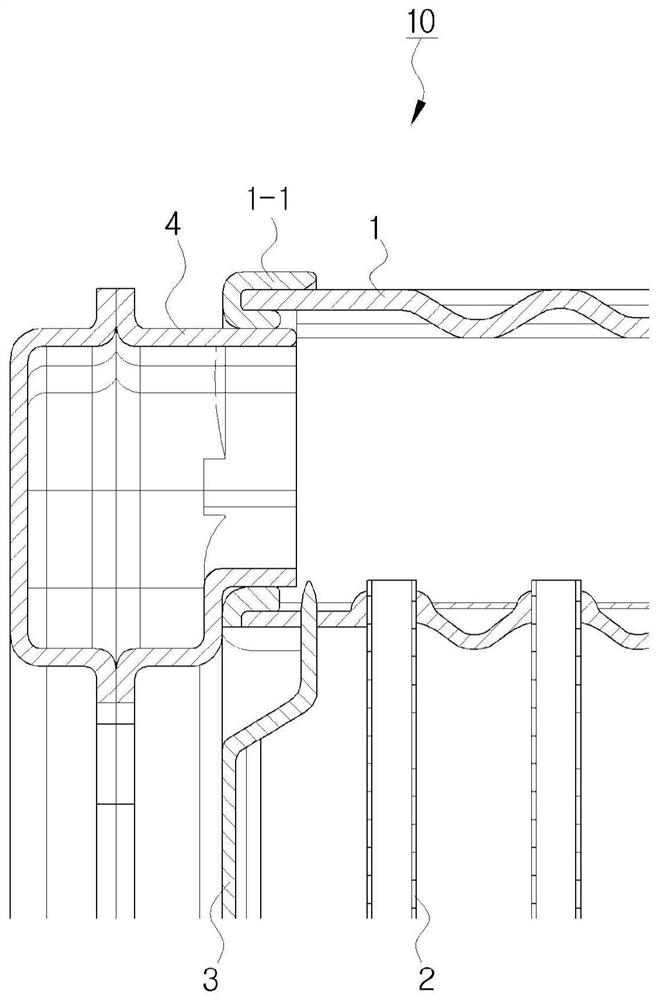
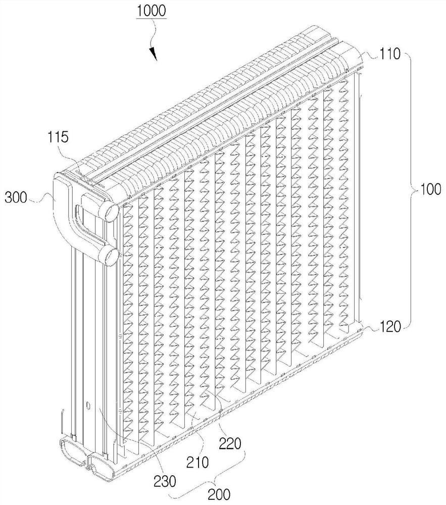
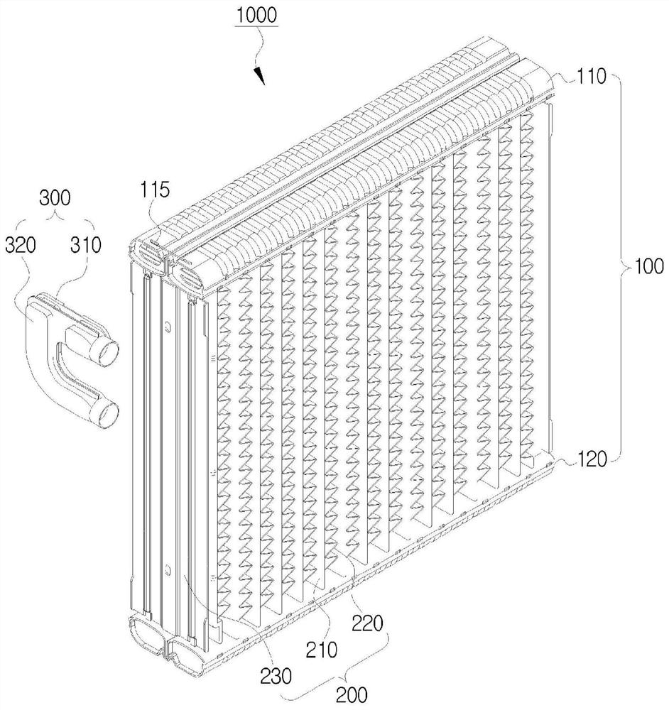
[0040] figure 2 is a diagram illustrating a heat exchanger according to a first exemplary embodiment of the present invention in a perspective view, image 3 is another diagram illustrating the heat exchanger according to the first exemplary embodiment of the present invention in a perspective view, Figure 4 is a diagram illustrating a heat exchanger according to a first exemplary embodiment of the present invention in a partial sectional view, Figure 5 is another diagram illustrating the heat exchanger according to the first exemplary embodiment of the present invention in a partial sectional view, and Figure 6 is a diagram illustrating a fixed baffle of the heat exchanger according to the first exemplary embodiment of the present invention in a sectional view.

[0041] refer to Figure 2 to ...


PUM


Abstract

The present invention relates to a heat exchanger and, more specifically, to a heat exchanger, which has a manifold coupled to a header tank, allowing easy attachment between a manifold and a header tank as well as avoidance of interference between the manifold and a support by forming a baffle-shaped fixed baffle on one length direction of the header tank to which the manifold is inserted and attached.

Description

technical field [0001] The present invention relates to a heat exchanger, and more particularly, to a heat exchanger in which a baffle-like fixed baffle inserted into and combined with a manifold is formed on one side of a header tank in the length direction to The manifold is coupled to the header tank so that the manifold and the header tank can be easily combined with each other and interference between the manifold and the support can be avoided. Background technique [0002] figure 1 is a diagram illustrating a partial sectional view of a conventional heat exchanger 10 . [0003] refer to figure 1 , a conventional heat exchanger 10 includes header tanks 1 formed to be spaced apart from each other and tubes 2 with both ends inserted and fixed between the header tanks 1, and a plurality of fins (fins) may be inserted between the tubes 2. ) to improve heat exchange efficiency. [0004] In addition, the heat exchanger 10 may include support members 3 positioned at both ...

Claims


Application Information

Patent Timeline
Patent Type & Authority Applications(China)
IPC IPC(8): F28F9/02F28F9/22
CPCF28F9/0231F28D1/05391F28F1/126F28F9/0256F28F9/22
Inventor 李德浩
Owner HANON SYST
Why Eureka
Try Eureka