
Joint connection auxiliary equipment for low-voltage cable

A technology for joint connection and auxiliary equipment, which is applied in the direction of connecting/terminating cable equipment, connection, and connection and connection by deformation, which can solve the problems of high labor intensity and long time.

Active Publication Date: 2021-02-02
山东诺环建工有限公司
View PDF7 Cites 1 Cited by
  • Summary
  • Abstract
  • Description
  • Claims
  • Application Information

AI Technical Summary

Problems solved by technology

[0003] For the connection of low-voltage cables, when the crimping method is used, the two cable ends to be connected need to be stripped first, straightened, and then the two ends are inserted into the cable joints, and finally squeezed and integrated. The prior art Among them, the straightening operation of the cable end requires multiple operators to spend nearly a day on the operation, which is labor-intensive and time-consuming

Method used

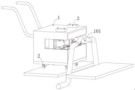
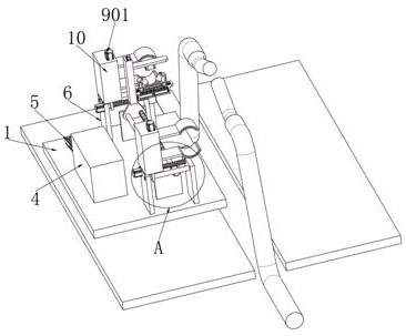
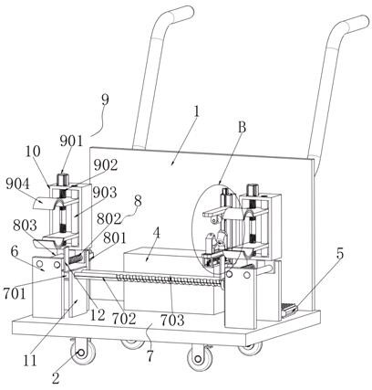

Image

  • Joint connection auxiliary equipment for low-voltage cable
  • Joint connection auxiliary equipment for low-voltage cable
  • Joint connection auxiliary equipment for low-voltage cable

Examples


Embodiment Construction

[0029] The following will clearly and completely describe the technical solutions in the embodiments of the present invention with reference to the accompanying drawings in the embodiments of the present invention. Obviously, the described embodiments are only some, not all, embodiments of the present invention.

[0030] In describing the present invention, it should be understood that the terms "upper", "lower", "front", "rear", "left", "right", "top", "bottom", "inner", " The orientation or positional relationship indicated by "outside", etc. is based on the orientation or positional relationship shown in the drawings, and is only for the convenience of describing the present invention and simplifying the description, rather than indicating or implying that the referred device or element must have a specific orientation, so as to Specific orientation configurations and operations, therefore, are not to be construed as limitations on the invention.

[0031] refer to Figure 1-...


PUM


Abstract

The invention discloses joint connection auxiliary equipment for a low-voltage cable, which comprises a box body. A U-shaped opening is formed in the side wall of the box body, and a first driving mechanism, a second driving mechanism, a clamping mechanism, a straightening mechanism, a first mounting shell, a second mounting shell, two pressing type switches, a power source and a controller are arranged in the box body; two parallel first rack plates are symmetrically welded to the side wall of the bottom of the box body, a first driving mechanism used for driving the straightening mechanism to move is arranged on the first rack plates, and the straightening mechanism is arranged on the second mounting shell and used for straightening the cable inner core. Four second rack plates are welded to the side wall of the bottom in the box body, and every two of the four second rack plates are symmetrical and located on the two sides of the two first rack plates. The invention relates to the technical field of cable connection auxiliary equipment, and straightening operation can be conducted on two low-voltage cable ends before wiring, so that the labor intensity is greatly reduced, and the wiring efficiency is improved.

Description

technical field [0001] The invention relates to the technical field of cable connection auxiliary equipment, in particular to a low-voltage cable joint connection auxiliary equipment. Background technique [0002] After the cable is laid, in order to make it a continuous line, each section of the line must be connected as a whole, so it is necessary to use cable joints to connect every two cables. The common way to connect medium and low voltage cable conductors is crimping. The cable joints in the middle of the cable line are called intermediate joints, and the cable joints at both ends of the line are called terminal heads. The cable joint is used to lock and fix the incoming and outgoing lines, and play the role of waterproof, dustproof and shockproof. [0003] For the connection of low-voltage cables, when the crimping method is used, the two cable ends to be connected need to be stripped first, straightened, and then the two ends are inserted into the cable joints, and...

Claims


Application Information

Patent Timeline
Patent Type & Authority Applications(China)
IPC IPC(8): H02G1/14B21F1/02H01R43/28H01R43/04
CPCH02G1/14B21F1/02H01R43/28H01R43/04
Inventor 王平堂王佳
Owner 山东诺环建工有限公司
Learn More