Transformer structure and manufacturing method thereof

A manufacturing method and technology of transformers, which are applied in the manufacture of inductors/transformers/magnets, transformer/inductor shells, transformers/inductor magnetic cores, etc., can solve the problems of impeding the flow of potting glue and unfavorable mold cavity air bubble discharge.

Active Publication Date: 2021-02-02
DELTA ELECTRONICS (SHANGHAI) CO LTD
View PDF16 Cites 0 Cited by
  • Summary
  • Abstract
  • Description
  • Claims
  • Application Information

AI Technical Summary

Problems solved by technology

However, the openings on the prefabricated isolation structure can easily hinder the flow of potting compound, which is not conducive to the discharge of air bubbles inside the mold cavity, and is easy to generate defects inside, so the application at higher voltages is limited.

Method used


Image

  • Transformer structure and manufacturing method thereof
  • Transformer structure and manufacturing method thereof
  • Transformer structure and manufacturing method thereof

Examples


Embodiment Construction

[0068] Some typical embodiments embodying the features and advantages of the present application will be described in detail in the description in the following paragraphs. It should be understood that this case can have various changes in different aspects without departing from the scope of this case, and the descriptions and drawings therein are used for illustration in nature rather than for limiting this case.

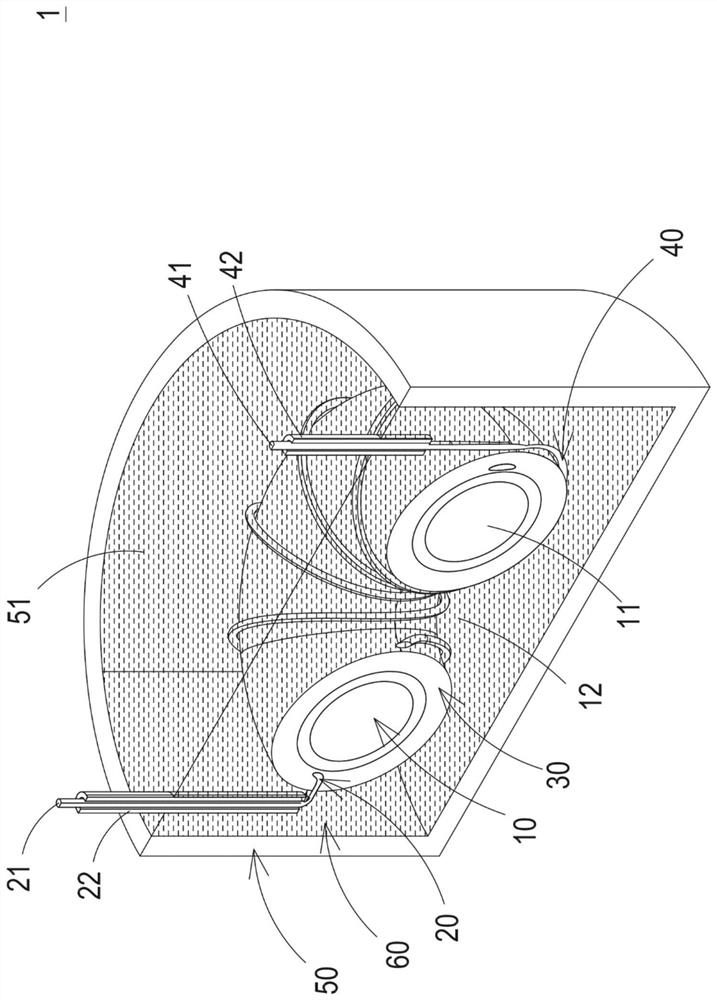
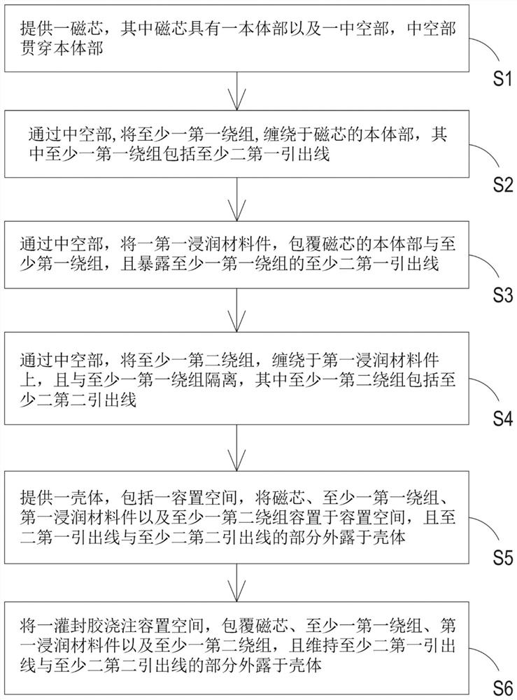
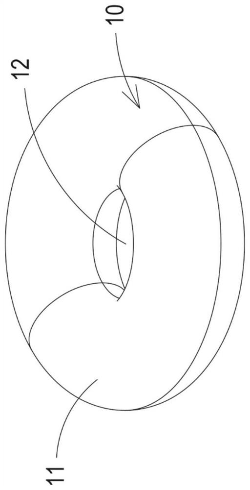
[0069] figure 1 It is a cross-sectional structure diagram of the transformer structure of the first preferred embodiment of the present application. figure 2 To disclose the manufacturing method of the transformer structure of the first preferred embodiment of the present case. Figure 3A to Figure 3E It is a schematic diagram of the transformer structure in various stages of manufacture in the first preferred embodiment of the present case. In this embodiment, the transformer structure 1 includes a magnetic core 10 , at least one first winding 20 , a first wet...


PUM


Abstract

The invention relates to a transformer structure and a manufacturing method thereof. The transformer structure comprises a magnetic core, a first winding, a first infiltration material piece, a secondwinding, a shell and a pouring sealant. The magnetic core is provided with a body part and a hollow part which penetrates through the body part. The first winding is wound on the body part of the magnetic core through the hollow part and comprises two first leading-out wires. The first infiltration material piece wraps the body part and the first winding through the hollow part, and exposes the two first leading-out wires. The second winding is wound on the first infiltration material piece through the hollow part, is isolated from the first winding and comprises two second leading-out wiresat the same time. The shell comprises an accommodating space, and the magnetic core, the first winding, the first infiltration material piece and the second winding are accommodated in the accommodating space. The pouring sealant is poured into the accommodating space, and the at least two first leading-out wires and the at least two second leading-out wires are maintained to be exposed out of theshell. The withstand voltage and the partial discharge extinguishing voltage of the transformer structure are remarkably improved, and the size of the transformer structure is reduced.

Description

technical field [0001] This case is about a transformer structure, especially a miniaturized transformer structure with high insulation performance and its manufacturing method. Background technique [0002] In recent years, transformers have been widely used in medium-voltage power distribution devices, such as IGBT drive, protection, power transformers, etc. All kinds of systems require a large number of transformers in the modular design. In order to increase the power density of the application system, it is necessary to reduce the size of the transformer. [0003] In low-voltage systems, air is often used as the insulation medium for transformer insulation. Since the insulation level is not high, the volume of the product is often acceptable. However, in the medium-voltage system, the requirements for the withstand voltage (withstand voltage) and partial discharge (PD) level of the transformer insulation are relatively high. Traditional medium-voltage transformers oft...

Claims


Application Information

Patent Timeline
Patent Type & Authority Applications(China)
IPC IPC(8): H01F27/02H01F27/28H01F27/32H01F41/00H01F41/12
CPCH01F27/327H01F27/28H01F27/02H01F27/022H01F41/005H01F41/127H01F27/2823H01F27/2895H01F27/24H01F41/06
Inventor 应建平王亮汪强刘腾曾永董建星
Owner DELTA ELECTRONICS (SHANGHAI) CO LTD
Why Eureka
Try Eureka