Finite element modeling method for forged steel piston

A modeling method and finite element technology, applied in 3D modeling, image data processing, special data processing applications, etc., can solve the problem of not truly reflecting the stress of the connection between the piston ring body and the body, and not being able to truly present the piston Problems such as ring body connection relationship and inaccurate finite element analysis results have been achieved to improve design and development efficiency, accurate technical support, and high work efficiency

Active Publication Date: 2021-02-02
BINZHOU BOHAI PISTON CO LTD
View PDF5 Cites 0 Cited by
  • Summary
  • Abstract
  • Description
  • Claims
  • Application Information

AI Technical Summary

Problems solved by technology

It solves the problem that the finite element modeling method of the single-weld laser welding integral forged steel piston in the prior art cannot truly present the connection relationship between the piston ring body and the body, resulting in inaccurate finite element analysis results and unable to truly reflect the piston ring body The stress and deformation of the connection part with the main body

Method used


Image

  • Finite element modeling method for forged steel piston
  • Finite element modeling method for forged steel piston
  • Finite element modeling method for forged steel piston

Examples


Embodiment Construction

[0028] In order to enable those skilled in the art to better understand the technical solutions in the present invention, the technical solutions in the embodiments of the present invention will be clearly and completely described below in conjunction with the drawings in the embodiments of the present invention. Obviously, the described The embodiments are only some of the embodiments of the present invention, not all of them.

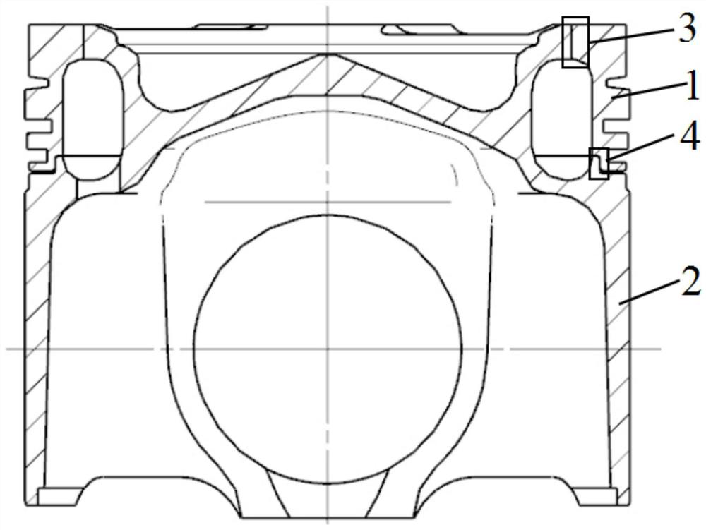
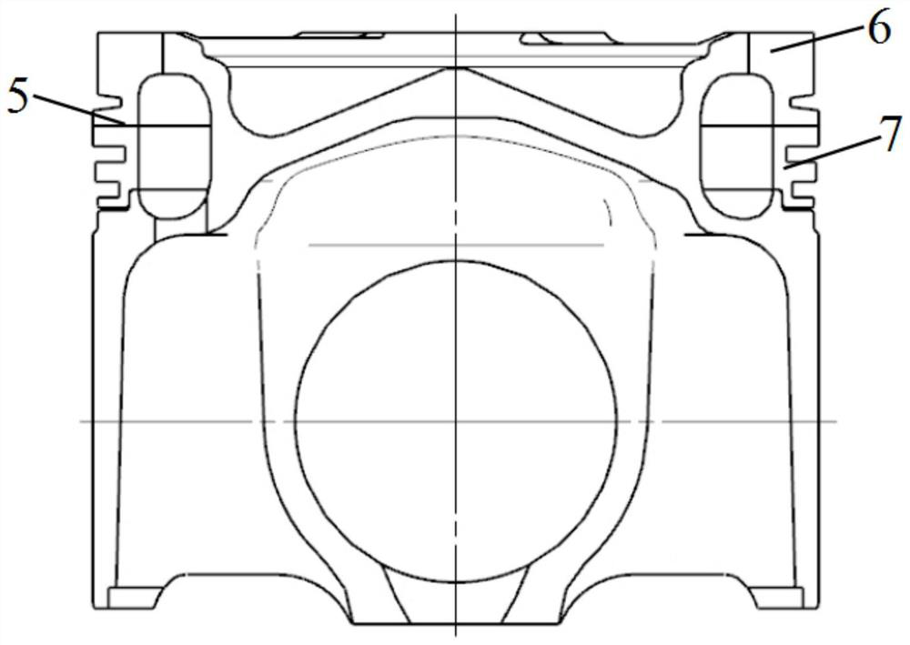
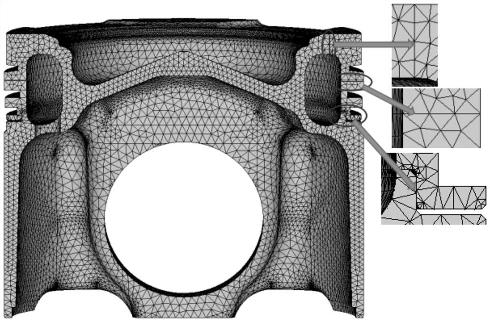
[0029] Such as Figure 1-3 As shown, a finite element modeling method of a forged steel piston specifically includes the following steps:

[0030] 1) Establish a three-dimensional model of the piston, and make the piston ring body 1 and the piston body 2 together, such as figure 1 As shown, the upper part is the welding area 3, and the lower part is the matching area 4; commonly used software includes: UG, Pro / E, CATIA, etc., using mature software, less investment, and high work efficiency.

[0031] The welding area 3 is where the outer cylindrical ...


PUM


Abstract

The invention discloses a finite element modeling method for a forged steel piston, which comprises the following steps: 1) establishing a three-dimensional model of the piston, and manufacturing a piston ring body and a piston body together, with the upper part being a welding area and the lower part being a matching area; 2) dividing the piston ring body into an upper part and a lower part at any part of the piston ring body by using a dividing surface; 3) importing the built piston three-dimensional model into finite element analysis software, adhering the upper part and the lower part of the piston ring body together by using a Boolean adhesion command, adding the upper part and the piston body of the piston ring body by using a Boolean addition command, and dividing grids; performingfollow-up loading calculation, establishing contact for the matching area, and reflecting the matching relation between the two sides of the matching area. According to the invention, the connection relation between the welding area and the matching area of the single-welding-seam laser welding integral forged steel piston can be truly presented, subsequent analysis and calculation are facilitated, and the analysis result is more accurate.

Description

technical field [0001] The invention relates to the field of finite element analysis and modeling, in particular to a finite element modeling method for a forged steel piston. The invention can accurately reflect the connection mode of a welding zone and a mating zone in a single welding seam laser welding integral forged steel piston. Background technique [0002] With the requirements of high power, low fuel consumption and low emission, the engine explosion pressure also increases, which puts forward higher requirements for piston performance. Although traditional aluminum pistons are widely used, their performance cannot meet the high-strength requirements of engines in many fields. Using forged steel pistons to replace traditional aluminum pistons is an inevitable choice to improve engine performance. [0003] The single-weld laser-welded integral forged steel piston is one of the commonly used forged steel piston structures. It is structurally composed of two parts: th...

Claims


Application Information

Patent Timeline
Patent Type & Authority Applications(China)
IPC IPC(8): G06F30/17G06F30/23G06T17/20G06F119/14
CPCG06F30/17G06F30/23G06T17/20G06F2119/14Y02T90/00
Inventor 张俊青刘世英郭庆元赵旭东李猛猛贾艳孟栋栋吴义民石小明马学军
Owner BINZHOU BOHAI PISTON CO LTD
Why Eureka
Try Eureka