
Display optical system for reducing ghosting and head-mounted display device

An optical system and display technology, applied in optics, optical components, instruments, etc., can solve the problems of good consistency in the visible light range, weight increase, low reflectivity, etc., and achieve easy popularization and application, reduction of ghost images, and high reliability Effect

Inactive Publication Date: 2021-02-02
SHENZHEN HUYNEW TECH CO LTD
View PDF0 Cites 3 Cited by
  • Summary
  • Abstract
  • Description
  • Claims
  • Application Information

AI Technical Summary

Problems solved by technology

The first is to coat the surface of the polarization control element with an AR (Anti-Reflection) layer or compound a layer of optical film with AR function, but these materials can only have a low reflectivity near 589nm (such as <0.7%, DNP LR Film), unable to maintain good consistency in the entire visible light range
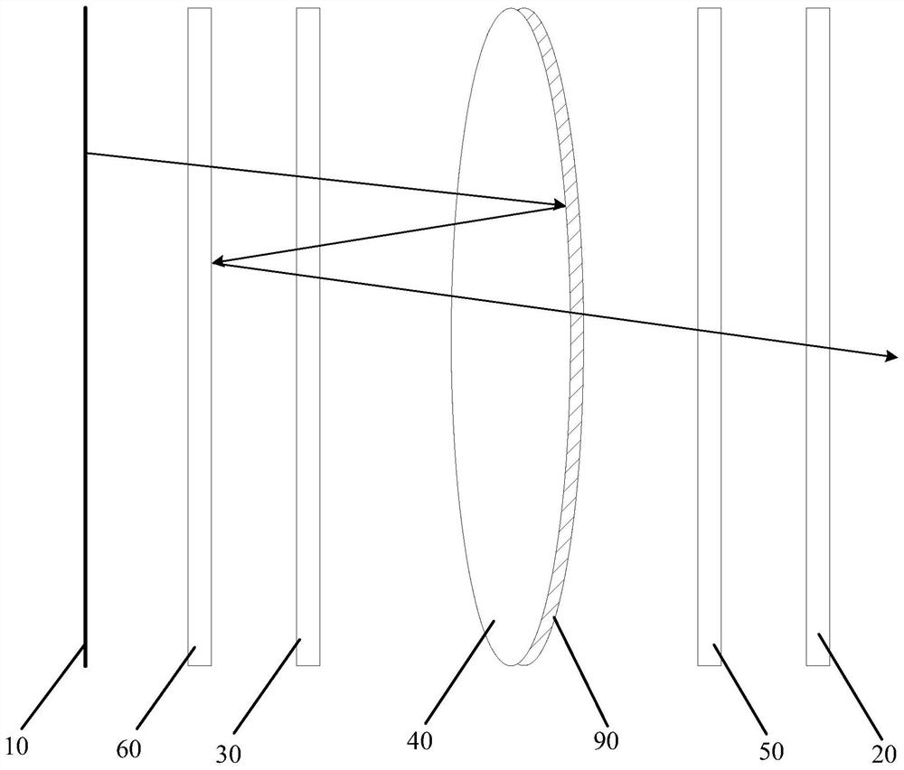
The second is to combine the quarter-wave plate (QWP) with the polarizing beam splitter (PBS), and then stick it on a substrate. This solution reduces an optical reflection surface, but the reflection of the remaining optical surface is still obvious , and the corresponding ghost plays a major role in the imaging
The third is to combine QWP and PBS, and stick them on the back surface of the lens at the same time, or stick them between two lenses. Although the corresponding reflection can be reduced, in order to meet the requirements of diopter and image quality, there are lenses Unfavorable factors such as thicker and increased weight limit its application in products

Method used


Image

  • Display optical system for reducing ghosting and head-mounted display device
  • Display optical system for reducing ghosting and head-mounted display device
  • Display optical system for reducing ghosting and head-mounted display device

Examples


Embodiment Construction

[0027] The following will clearly and completely describe the technical solutions in the embodiments of the present invention with reference to the accompanying drawings in the embodiments of the present invention. Obviously, the described embodiments are only part of the embodiments of the present invention, not all of them. Based on the embodiments of the present invention, all other embodiments obtained by persons of ordinary skill in the art without creative efforts fall within the protection scope of the present invention.

[0028] It should be noted that if there is a directional indication (such as up, down, left, right, front, back...) in the embodiment of the present invention, the directional indication is only used to explain the position in a certain posture (as shown in the accompanying drawing). If the specific posture changes, the directional indication will also change accordingly.

[0029] In addition, if there are descriptions involving "first", "second" and ...


PUM


Abstract

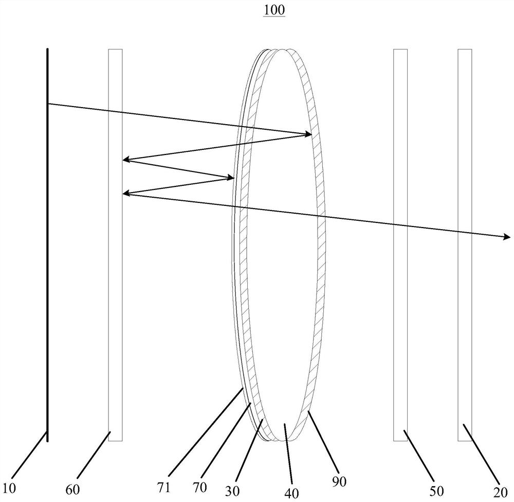
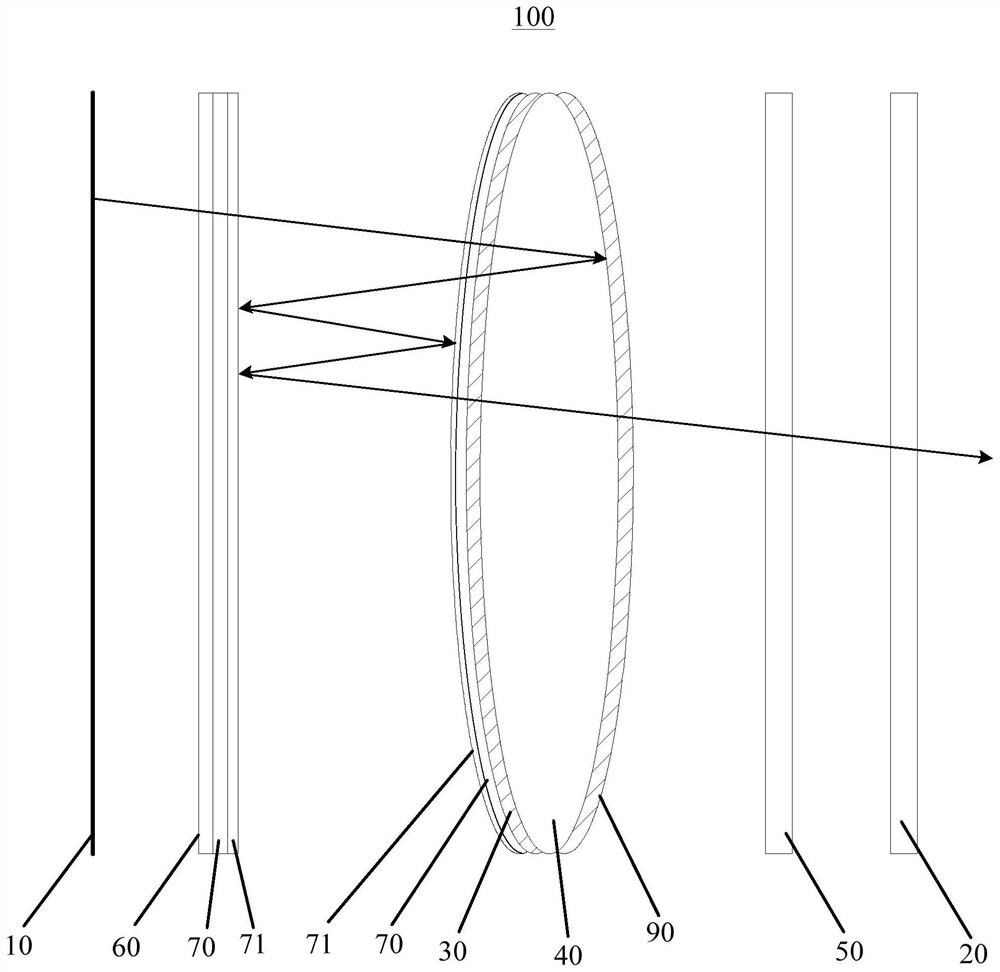
The invention discloses a display optical system for reducing ghosting and a head-mounted display device. The display optical system for reducing ghosting comprises a display screen, a polarization beam splitting element, a first polarization conversion element, a partial transmission and partial reflection element, a second polarization conversion element and a polarization piece which are arranged in sequence; the display optical system further comprises a lens arranged on the side, facing the display screen, of the partial transmission and partial reflection element; the lens is attached tothe first polarization conversion element, and / or the lens is attached to the polarization light splitting element; the first polarization conversion element and the polarization light splitting element are arranged at intervals, a substrate is arranged on the surface, exposed in the air, of the first polarization conversion element, and an antireflection film is arranged on the substrate. According to the technical scheme, ghosting caused by Fresnel reflection generated when interfaces of different elements in a folded light path are exposed in air can be reduced, so that the image quality of the display optical system is improved, and the display optical system has the characteristic of light weight.

Description

technical field [0001] The invention relates to the technical field of optical display, in particular to a display optical system and a head-mounted display device for reducing ghost images. Background technique [0002] In near-eye display NED (Near eye display) or head mounted display HMD (Head mounted display) optical system, optical film (optical film) is more and more widely used because of its functionality and high cost performance, such as polarization control element polarizer , compensation sheet, etc., play an important role in the folding optical path (pancake). However, these components will produce Fresnel reflection when exposed to the air (referring to the phenomenon that part of the light will be reflected when light is incident on the interface of two media with different refractive indices), which in turn will cause ghost images and affect image quality. [0003] There are mainly three ways to solve this problem. The first is to coat the surface of the p...

Claims


Application Information

Patent Timeline
Patent Type & Authority Applications(China)
IPC IPC(8): G02B27/01G02B1/11
CPCG02B27/0172G02B1/11
Inventor 王旭陈益千于佳张韦韪
Owner SHENZHEN HUYNEW TECH CO LTD
Learn More