
Lighting device

A lighting device and collimated light technology, which is applied in the direction of lighting devices, components of lighting devices, lighting and heating equipment, etc., can solve the problems of poor light output effect, achieve suppression of glare, suppression of direct viewing glare, and solve the problem of poor light output effect. poor effect

Inactive Publication Date: 2021-02-02
QINGDAO YEELINK INFORMATION TECH
View PDF0 Cites 1 Cited by
  • Summary
  • Abstract
  • Description
  • Claims
  • Application Information

AI Technical Summary

Problems solved by technology

[0004] The main purpose of the present invention is to provide a lighting device to solve the technical problem that the lighting device in the prior art has poor light output effect when simulating sky lights

Method used


Image

  • Lighting device
  • Lighting device
  • Lighting device

Examples


Embodiment Construction

[0040] It should be noted that the embodiments in the present application and the features of the embodiments may be combined with each other in the case of no conflict. The present invention will be described in detail below with reference to the accompanying drawings and in conjunction with the embodiments.

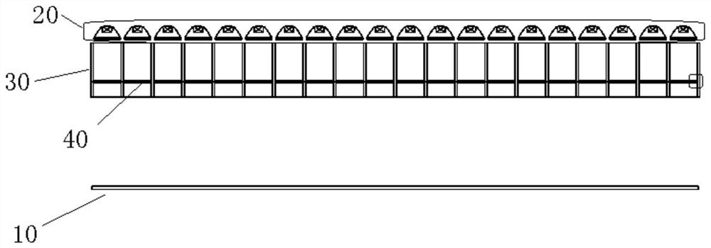
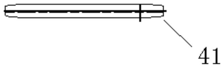
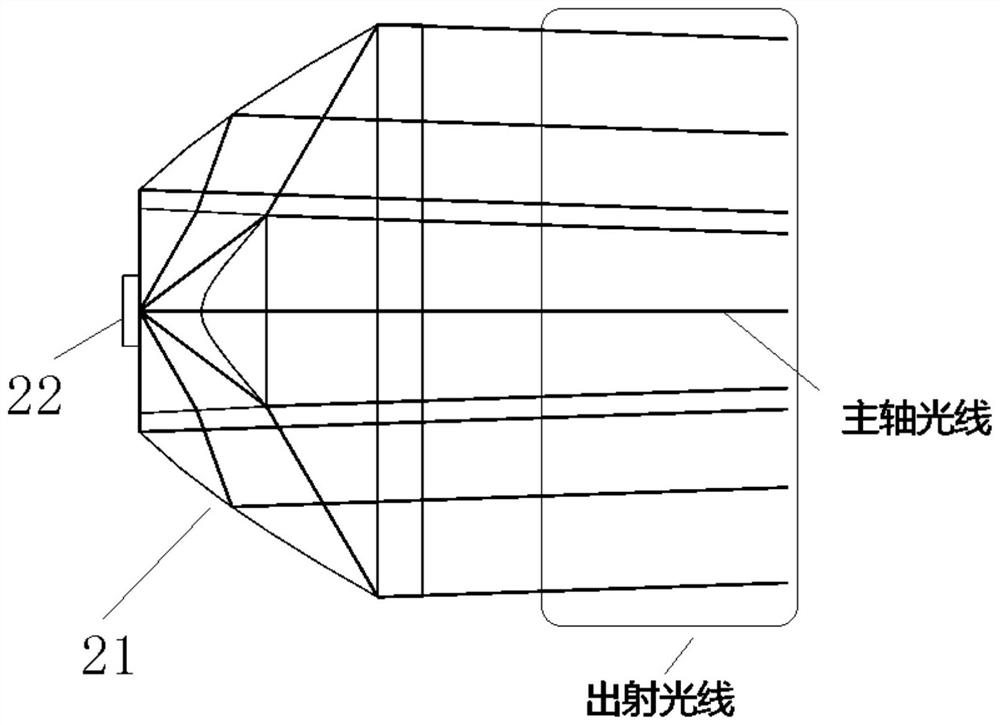
[0041] like Figure 1 to Figure 20 As shown, the embodiment of the present invention provides a lighting device including a Rayleigh scattering plate 10 , a collimated light generator 20 , a beam restrictor 30 and a beam angle expander 40 . The collimated light generator 20 is disposed opposite to the Rayleigh scattering plate 10. Specifically, the collimated light generator 20 refers to a light generator for providing a collimated light beam. The beam restraint 30 is disposed opposite the collimated light generator 20, the beam restraint 30 is located between the Rayleigh scattering plate 10 and the collimated light generator 20, the beam restraint 30 has a light rest...


PUM


Abstract

The invention provides a lighting device. The lighting device comprises a Rayleigh scattering plate, a collimated light generator arranged opposite to the Rayleigh scattering plate and used for providing collimated light beams, a light beam constraint device arranged opposite to the collimated light generator, located between the Rayleigh scattering plate and the collimated light generator, provided with a light constraint channel, and used for eliminating light with a preset angle, and a light beam angle expander arranged in the light constraint channel of the light beam constraint device andused for enabling the collimated light beams emitted by the collimated light generator to deviate. Through the technical scheme provided by the invention, the technical problem of poor light emittingeffect when the lighting device simulates the sky lamp in the prior art can be solved.

Description

technical field [0001] The present invention relates to the technical field of lighting devices, and in particular, to a lighting device. Background technique [0002] At present, with the progress of society and the improvement of the quality of life, people pay more and more attention to the quality of life and pursue a healthy living environment. It is in this environment that in recent years, the home lighting industry has begun to appear a new form of lamps - sky lamps, or also known as blue sky lamps. The main features of this simulated sky lamp are reflected in the two points of simulating the visual effect of the sky and simulating the parallel illumination of the sun's rays. There are two main types of simulated sky lamps on the market: one only focuses on simulating the visual effect of the sky, giving up the approximate simulation of parallel illumination of the sun's rays; Approximate simulation of parallel illumination. [0003] However, for the second case, ...

Claims


Application Information

Patent Timeline
Patent Type & Authority Applications(China)
IPC IPC(8): F21S2/00F21V5/04F21V9/00G02B13/00G02B6/32
CPCF21S2/00F21V5/04F21V9/00G02B13/00G02B6/32
Inventor 王国建
Owner QINGDAO YEELINK INFORMATION TECH
Learn More