Eureka AIR delivers breakthrough ideas for toughest innovation challenges, trusted by R&D personnel around the world.

Concrete strength detection equipment for post-disaster house safety identification

A technology for concrete strength and testing equipment, applied in mechanical equipment, strength characteristics, measuring devices, etc., can solve problems such as inconvenience during testing, and achieve the effect of large measurement coverage, guaranteed testing stability, and large height adjustment range.

Inactive Publication Date: 2021-02-02
张红卫
View PDF0 Cites 0 Cited by
  • Summary
  • Abstract
  • Description
  • Claims
  • Application Information

AI Technical Summary

Problems solved by technology

[0007] Aiming at the above-mentioned shortcomings existing in the prior art, the present invention provides a concrete strength detection device for post-disaster housing safety appraisal, which can effectively overcome the existing existing detection devices in the prior art. The way to detect the concrete strength of the house is inconvenient for the detection of positions at different heights

Method used


Image

  • Concrete strength detection equipment for post-disaster house safety identification
  • Concrete strength detection equipment for post-disaster house safety identification
  • Concrete strength detection equipment for post-disaster house safety identification

Examples


Embodiment 1

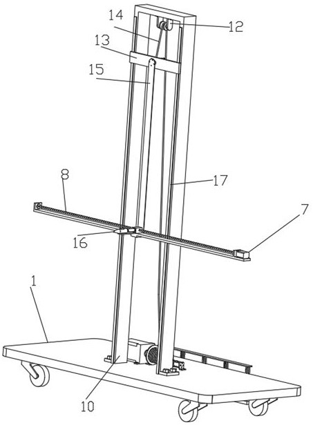
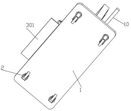
[0039] Such as Figure 1-8Shown is a concrete strength testing device for post-disaster housing safety appraisal, including a bottom plate 1 and a rebound tester 16. The bottom of the bottom plate 1 is symmetrically fixed with universal wheels 2, and the front side wall of the bottom plate 1 is connected with a brake for equipment. Stable structure 3. The stable structure 3 includes a stable plate 301, a slide bar 302, a first horizontal plate 303, a bump 304, a spring 305, and a spring 305. The stable plate 301 is fixedly connected to the bottom plate 1 through bolts, and the bumps 304 are fixedly connected. There is a first horizontal plate 303, the top of the first horizontal plate 303 is evenly and fixedly connected with a spring 305, the top of the spring 305 is fixedly connected with a top plate 306, the bottom of the top plate 306 is evenly and fixedly connected with a slide bar 302, and the bottom of the slide bar 302 runs through the first The horizontal plate 303 is ...

Embodiment 2

[0042] Embodiment 2 is a further improvement to Embodiment 1.

[0043] Such as Figure 1-8 Shown is a concrete strength testing device for post-disaster housing safety appraisal, including a bottom plate 1 and a rebound tester 16. The bottom of the bottom plate 1 is symmetrically fixed with universal wheels 2, and the front side wall of the bottom plate 1 is connected with a brake for equipment. The stable structure 3, the stable structure 3 comprises a stable plate 301, a slide bar 302, a first horizontal plate 303, a bump 304, a spring 305 and a spring 305, the first horizontal plate 303 is fixedly connected between the bumps 304, the first horizontal plate The top of the 303 is evenly and fixedly connected with a spring 305, the top of the spring 305 is fixedly connected with a top plate 306, the bottom of the top plate 306 is evenly and fixedly connected with a slide bar 302, and the bottom of the slide bar 302 runs through the first horizontal plate 303 and is fixedly con...

Embodiment 3

[0045] Embodiment 3 is a further improvement to Embodiment 1.


PUM


Abstract

The invention relates to the technical field of concrete strength detection, in particular to concrete strength detection equipment for post-disaster house safety identification. The concrete strengthdetection equipment comprises a bottom plate, wherein universal wheels are arranged on the bottom plate, the bottom plate is provided with a stable structure, a lifting structure and a brake structure, the lifting structure comprises a first driving motor, an n-shaped frame, a fixed pulley, a sliding plate and a steel rope, the first driving motor is provided with a winding roller connected withthe steel rope, the n-shaped frame is provided with the fixed pulley, the steel rope is provided with the sliding plate, the sliding plate is provided with a rotating structure, the rotating structurecomprises a third driving motor and a second L-shaped supporting plate, the second L-shaped supporting plate is connected with the sliding plate, the second L-shaped supporting plate is provided withthe third driving motor, the third driving motor is provided with a rotating rod, the rotating rod is provided with a connecting circular plate, the connecting circular plate is provided with a firstL-shaped supporting plate, the first L-shaped supporting plate is provided with an adjusting structure, the adjusting structure is connected with an electric push rod and a supporting plate, and theelectric push rod is provided with a resiliometer. According to the concrete strength detection equipment, the height adjusting range of the resiliometer is wider, and the resiliometer is convenient to use when positions with different heights are detected.

Description

technical field [0001] The invention relates to the technical field of concrete strength detection, in particular to a concrete strength detection device for post-disaster house safety appraisal. Background technique [0002] Geological disasters refer to geological processes or geological phenomena that are formed under the action of natural or human factors and cause losses to human life and property and damage to the environment. The distribution of geological disasters in time and space changes, which is not only restricted by the natural environment, but also related to human activities, and is often the result of the interaction between humans and nature. [0003] When a geological disaster occurs, it is easy to cause damage to the house. After the disaster, it is necessary to carry out quality inspection. Building inspection refers to testing the materials, components, equipment, and the quality and function of the construction project in accordance with relevant nat...

Claims


Application Information

Patent Timeline
IPC IPC(8): F16M11/04F16M11/18F16M11/42G01N3/52G01N3/02B66D1/74B66D1/12H02K7/06
CPCB66D1/7447F16M11/045F16M11/046F16M11/18F16M11/42F16M2200/08G01N3/02G01N3/52H02K7/06
Inventor 张红卫
Owner 张红卫
Why Eureka
Eureka Blog
Learn More