
Pile foundation structure of precast pile and intelligent auxiliary construction method

A technology of prefabricated piles and pile foundations, which is applied in foundation structure engineering, sheet pile walls, buildings, etc., can solve the problems of increasing the lateral stability of high-pile foundations, failing to fix prefabricated piles, and reducing the free length of foundations. Stable effect, scientific and reasonable construction process, and the effect of reducing construction errors

Active Publication Date: 2021-02-02
中交四航局港湾工程设计院有限公司
View PDF12 Cites 0 Cited by
  • Summary
  • Abstract
  • Description
  • Claims
  • Application Information

AI Technical Summary

Problems solved by technology

[0003] At present, there are very few technical solutions for stabilizing prefabricated piles. The invention patent with application number 201410660120.4 discloses a kind of embedding of high pile foundation pile foundation, but the invention aims to reduce the free length of the foundation and increase the foundation of high piles Lateral stability, and failed to effectively fix the prefabricated piles

Method used


Image

  • Pile foundation structure of precast pile and intelligent auxiliary construction method
  • Pile foundation structure of precast pile and intelligent auxiliary construction method
  • Pile foundation structure of precast pile and intelligent auxiliary construction method

Examples


Embodiment Construction

[0039] The present invention will be further described below in conjunction with the accompanying drawings and embodiments.

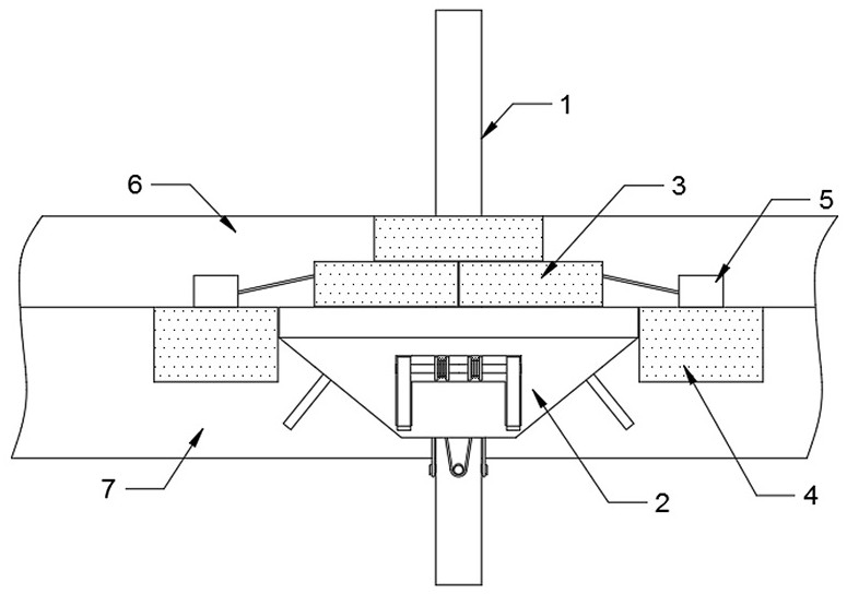
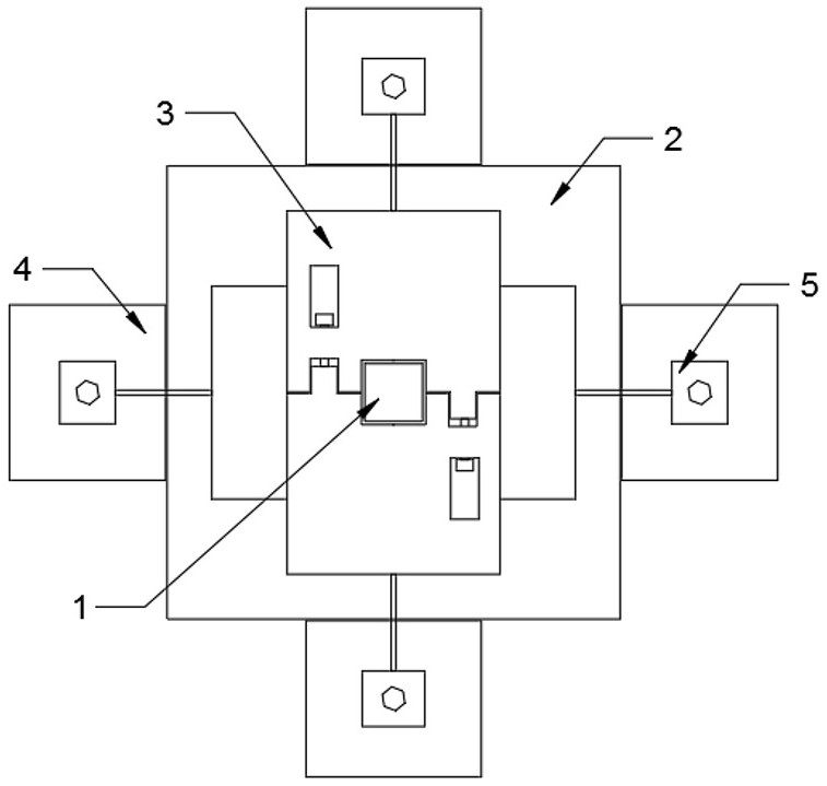
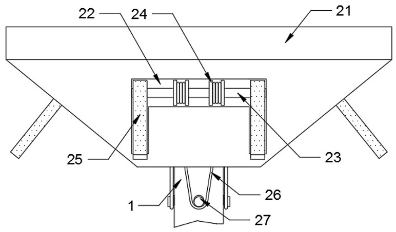
[0040] Please refer to figure 1 , figure 2 , image 3 , Figure 4 , Figure 5 , Figure 6 , Figure 7 , Figure 8 and Figure 9 ,in, figure 1 A schematic diagram of the overall front view structure provided by the present invention; figure 2 A schematic diagram of the overall top view structure provided by the present invention; image 3 One of the schematic diagrams of the deposition block structure provided by the present invention; Figure 4The second schematic diagram of the sediment block structure provided by the present invention; Figure 5 The third schematic diagram of the sediment block structure provided by the present invention; Figure 6 Schematic diagram of the top view structure of the deposition block provided by the present invention; Figure 7 Schematic diagram of the balance block structure provided by the present inven...


PUM


Abstract

The invention provides a pile foundation structure of a precast pile and an intelligent auxiliary construction method. The pile foundation structure comprises a precast column, a covering layer and arock layer, wherein the top face of the rock layer is covered with the covering layer; a deposition block capable of achieving linkage, expansion and positioning is arranged inside the rock layer in aburied mode, the precast column is inserted in the central position of the deposition block in a matched and penetrating mode, and the positions, located outside the precast column, of the top face of the deposition block are provided with balance blocks capable of achieving butt joint, fastening and fixing in a sleeved mode; and four position correcting blocks are symmetrically placed on the positions, located on the side edges of the deposition block, of the surface of the rock layer, and fastening mechanisms capable of achieving double fastening, fixing and connecting are fixed to the surfaces of the position correcting blocks. According to the pile foundation structure of the precast pile and the intelligent auxiliary construction method, the deposition block is adopted as a pile foundation positioning foundation, the problem that an existing pile foundation adopts long-degree-of-freedom penetrating insertion to form a fixed foundation in order to guarantee positioning stability is effectively solved, and the pile foundation structure is more suitable for pile foundation fixing in an area with the shallow covering layer; and meanwhile, degree-of-freedom limiting on the precastcolumn is increased upwards through the balance blocks, and opposite pulling force is formed in cooperation with the position correcting blocks and the fastening mechanisms, so that the side supportstabilizing effect on the precast column is greatly improved.

Description

technical field [0001] The invention relates to the technical field of hydraulic pile foundations, in particular to a prefabricated pile foundation structure and an intelligent auxiliary construction method. Background technique [0002] Pile foundation structure is one of the important forms of foundation structure in water transport engineering, and it is widely used in wharf structures. Because there will be many safety problems if cast-in-place piles are used in wharf, only prefabricated piles can be used. For the pile foundation bearing horizontal force or moment, its penetration depth must meet the conditions of elastic long piles, that is, for the pile foundation bearing horizontal force or moment, its penetration depth must meet a certain embedded depth requirement. In the area where the overburden is shallow, it is difficult for the prefabricated piles to sink to the design requirements. At this time, it is necessary to consider the necessary stabilization measures ...

Claims


Application Information

Patent Timeline
Patent Type & Authority Applications(China)
IPC IPC(8): E02D5/24E02D7/20E02D13/00E02D27/50
CPCE02D5/24E02D7/20E02D13/00E02D27/50
Inventor 程斌蒋国栋于晓岩李春保周海芳李冠星叶建科李芙蓉孙瞻
Owner 中交四航局港湾工程设计院有限公司
Learn More