
Four-hole button uniform perforating machine for clothes

A technology of punching machine and button, applied in the field of punching machine, can solve the problems of easy movement and poor drilling effect, etc.

Active Publication Date: 2021-02-02
凤城市瑞沃尔制衣有限公司
View PDF7 Cites 3 Cited by
  • Summary
  • Abstract
  • Description
  • Claims
  • Application Information

AI Technical Summary

Problems solved by technology

[0003] Existing drilling machine, as the patent notification number is that the Chinese patent of CN208231934U discloses a kind of garment accessory button drilling machine, comprises frame, workbench, shock-absorbing spring, electric telescopic rod, suction blower fan and cooling device, so The top of the frame is provided with a top cover; the above-mentioned patent has certain shortcomings. When punching a plurality of holes on the button, people need to manually take it out after punching a hole, and turn it in one direction, and then put it into the drilled hole. In the machine, and the button of the patent is easy to move when drilling, resulting in poor drilling effect

Method used


Image

  • Four-hole button uniform perforating machine for clothes
  • Four-hole button uniform perforating machine for clothes
  • Four-hole button uniform perforating machine for clothes

Examples


Embodiment 1

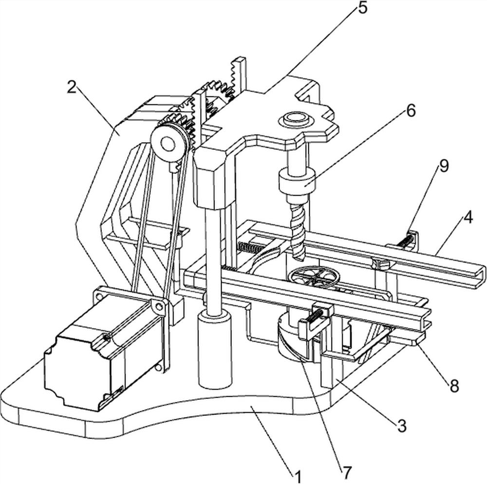
[0025] A four-hole button uniform punching machine for clothing, such as figure 1 As shown, it includes a bottom plate 1, a first support column 2, a second support column 3, a feeding frame 4, a lifting mechanism 5, an electric drill 6 and a rotating mechanism 7, and the top left side of the bottom plate 1 is fixedly connected to the front and rear symmetrically with the first support Column 2, a second support column 3 is fixedly connected front and rear symmetrically on the top right side of the bottom plate 1, a feeding rack 4 is connected between the top of the second support column 3, and a lifting mechanism 5 is arranged between the bottom plate 1 and the first support column 2, An electric drill 6 is installed at the bottom of the lifting mechanism 5 , and a rotating mechanism 7 is installed on the right side of the top of the bottom plate 1 .

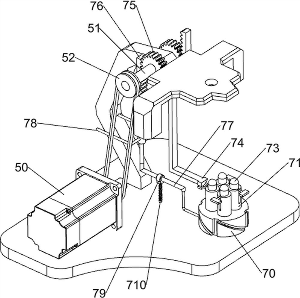
[0026] like figure 2 and image 3 As shown, the lifting mechanism 5 includes a servo motor 50, a first rotating shaft 51, ...

Embodiment 2

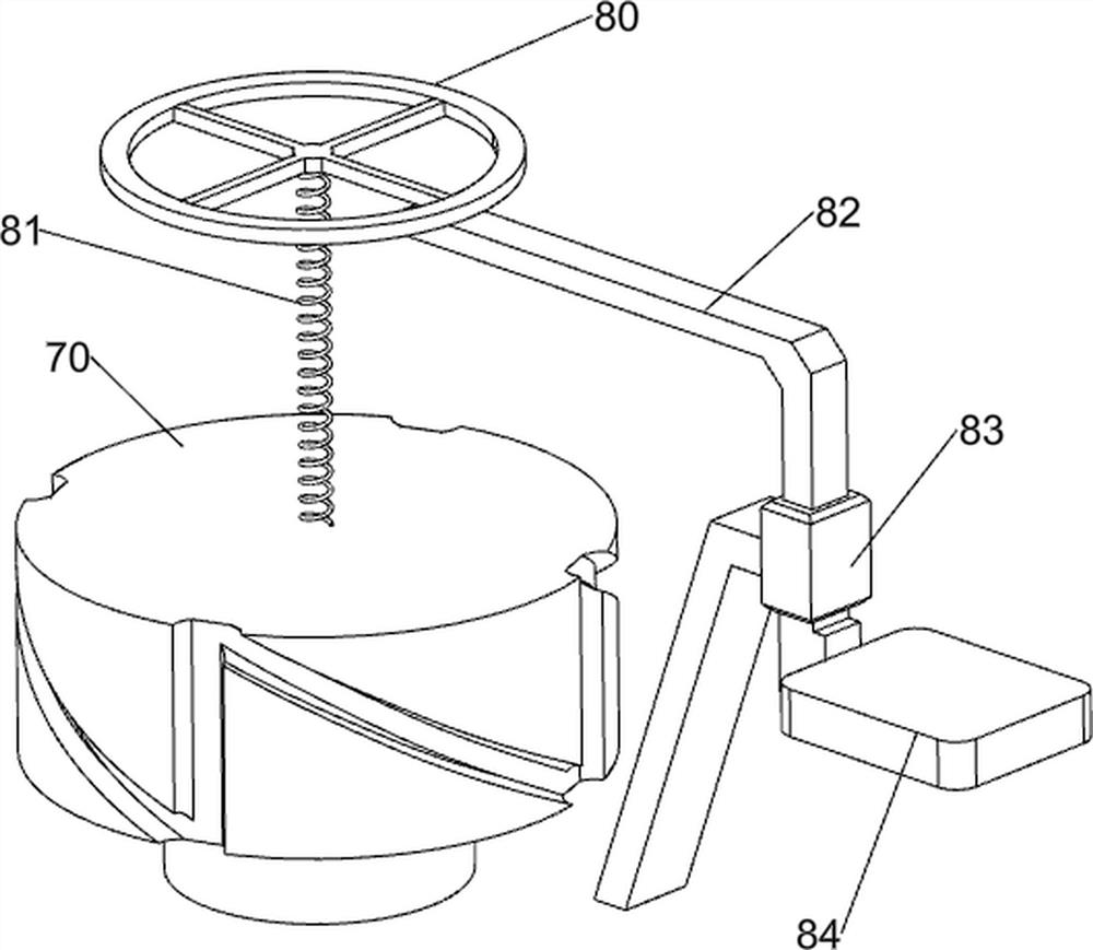
[0032] On the basis of Example 1, as Figure 7 As shown, it also includes a pressing mechanism 8. The pressing mechanism 8 includes a pressing plate 80, a fourth spring 81, a sliding plate 82, a second fixing frame 83 and a first fixing plate 84. The top of the sheave 70 is connected with a fourth The spring 81, the top of the fourth spring 81 is connected with a pressure plate 80, the middle of the top right side of the bottom plate 1 is fixedly connected with a second fixing frame 83, the second fixing frame 83 is slidably provided with a sliding plate 82, and the left end of the sliding plate 82 is fixed with the pressure plate 80 For connection, the lower end of the sliding plate 82 is connected with a first fixing plate 84 .

[0033] like Figure 8 As shown, it also includes a limiting mechanism 9, the limiting mechanism 9 includes a sliding block 90, a fifth spring 91, a second fixing plate 92, a clamping block 93, a sixth spring 94 and a fixing rod 95, and the feeding ...


PUM


Abstract

The invention relates to a perforating machine, and in particular, to a four-hole button uniform perforating machine for clothes. The four-hole button uniform perforating machine for the clothes, which can automatically perforate a button for multiple times, and can further fix the button, is provided. The four-hole button uniform perforating machine for the clothes comprises a bottom plate, second supporting columns, and a feeding frame, wherein first supporting columns are symmetrically and fixedly connected to one side of the top of the bottom plate; the second supporting columns are symmetrically and fixedly connected to the side, away from the first supporting columns, of the top of the bottom plate; and the feeding frame is connected between the tops of the second supporting columns.By using the four-hole button uniform perforating machine, the effects of automatically perforating the button for the multiple times and further fixing the button are achieved; after an electric drill bit descends and perforates the button, the button can be rotated by a quarter of a circle under the cooperation of a second sliding rod and a grooved wheel; and four holes can be uniformly formedin the button by repeating the operation for four times in this way.

Description

technical field [0001] The invention relates to a punching machine, in particular to a uniform punching machine for four-hole buttons for clothing. Background technique [0002] Buttons were first used as decorations. When people knew how to open buttonholes on buttons, the value of buttons was greatly improved. People use buttons to match the holes in clothes, so that we dress neatly and have a decent image. , so people need to punch holes in the buttons to connect the buttons and the clothes together by thread. [0003] Existing drilling machines, such as the Chinese patent with the patent publication number CN208231934U, discloses a button drilling machine for clothing accessories, including a frame, a workbench, a shock-absorbing spring, an electric telescopic rod, a suction fan and a heat sink, so The top of the frame is provided with a top cover; the above patent has certain disadvantages. When punching a plurality of holes on the button, people need to punch a hole, ...

Claims


Application Information

Patent Timeline
Patent Type & Authority Applications(China)
IPC IPC(8): B26F1/16B26D7/02B26D7/20
CPCB26F1/16B26D7/02B26D7/20
Inventor 黄庆兵
Owner 凤城市瑞沃尔制衣有限公司
Learn More