
Uniformly-spraying paint spraying device for hardware machining

A hardware and uniform technology, applied in the direction of spraying devices, spray booths, cleaning methods and utensils, etc., can solve the problems of poor spraying effect, inapplicable hardware of different lengths, low spraying efficiency, etc., and is conducive to large-scale promotion The effect of using, realizing recycling, and improving spraying efficiency

Inactive Publication Date: 2021-02-02
李禹
View PDF9 Cites 2 Cited by
  • Summary
  • Abstract
  • Description
  • Claims
  • Application Information

AI Technical Summary

Problems solved by technology

In order to prevent metal products from rusting, it is necessary to spray paint on the hardware, and the existing hardware often has the following problems in the process of painting: 1. Existing painting equipment often has missing spray or insufficient spraying when painting the hardware. The phenomenon of uniformity leads to poor spraying effect and low spraying efficiency; 2. The dust and impurities adhering to the surface of existing hardware during the painting process cannot be effectively treated, which can easily affect the spraying effect; 3. Existing painting The device does not have the function of recycling excess paint, which leads to easy waste of paint, which is not conducive to the concept of environmental protection and energy saving; 4. The existing painting equipment is not suitable for spraying operations on hardware of different lengths, resulting in a narrow application range of painting equipment, which is not conducive to Widespread use

Method used


Image

  • Uniformly-spraying paint spraying device for hardware machining
  • Uniformly-spraying paint spraying device for hardware machining
  • Uniformly-spraying paint spraying device for hardware machining

Examples


Embodiment Construction

[0030] In order to make the technical means, creative features, goals and effects achieved by the present invention easy to understand, the present invention will be further described below in conjunction with specific embodiments.

[0031] In the description of the present invention, it should be noted that the terms "upper", "lower", "inner", "outer", "front end", "rear end", "both ends", "one end", "another end" The orientation or positional relationship indicated by etc. is based on the orientation or positional relationship shown in the drawings, and is only for the convenience of describing the present invention and simplifying the description, rather than indicating or implying that the referred device or element must have a specific orientation, use a specific Azimuth configuration and operation, therefore, should not be construed as limiting the invention. In addition, the terms "first" and "second" are used for descriptive purposes only, and should not be understood ...


PUM


Abstract

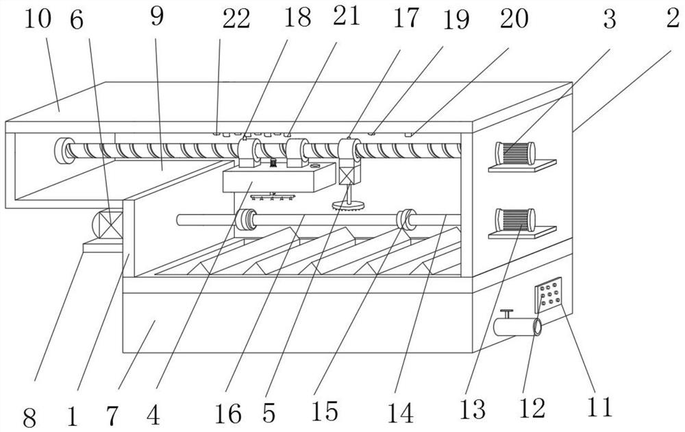
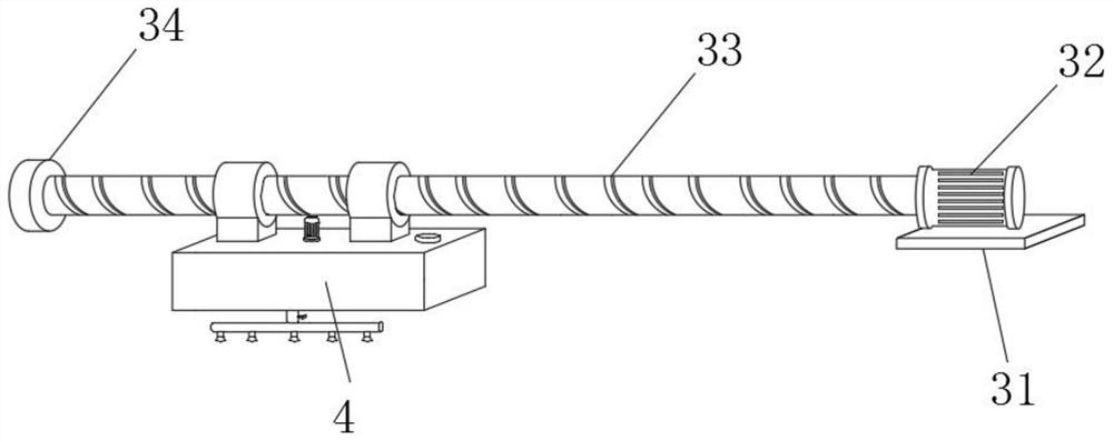
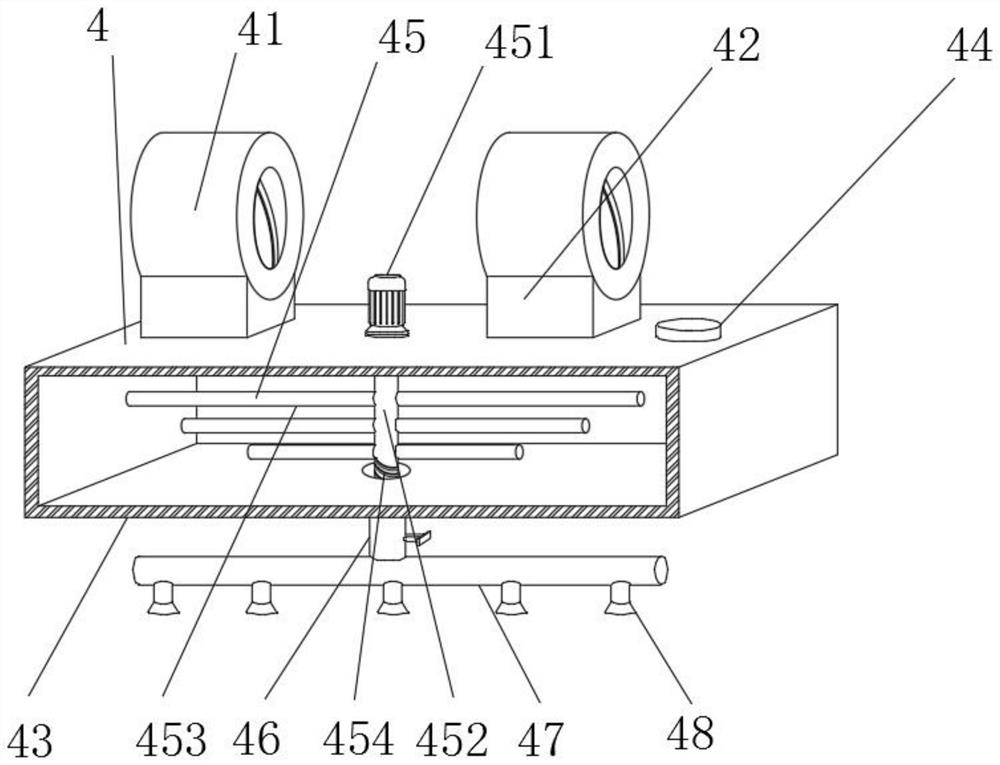
The invention discloses a uniformly-spraying paint spraying device for hardware machining. The paint spraying device comprises a recycling piece, a first vertical plate and a second vertical plate arefixedly installed on the left side and the right side of the upper end of the recycling piece correspondingly, and a third vertical plate is fixedly installed on the upper side of the left end of thefirst vertical plate. A top plate is fixedly installed at the upper end of the third vertical plate and the upper end of the second vertical plate jointly, a clamping piece penetrates through the middle of the first vertical plate, a driving device is fixedly installed on the upper portion of the right end of the second vertical plate, and the outer surface of the driving device is sleeved with aspraying piece and a cleaning device in a threaded mode. According to the uniformly-spraying paint spraying device for hardware machining, a driving motor and the driving device drive hardware to rotate and drive the spraying piece to move left and right correspondingly, so that the surface of the hardware can be sprayed more uniformly, waste liquid can be recycled by the recycling piece, and waste of spraying materials is avoided. In addition, the clamping piece can be suitable for clamping operation of hardware of different lengths, and the application range of the paint spraying equipmentis widened.

Description

technical field [0001] The invention relates to the technical field of hardware processing, in particular to a paint spraying device for uniform spraying of metal processing. Background technique [0002] Hardware: traditional hardware products, also known as "hardware". Refers to the five metals of gold, silver, copper, iron, and tin. After manual processing, it can be made into works of art or metal devices such as knives and swords. Hardware in modern society is more extensive, such as hardware tools, hardware parts, daily hardware, construction hardware and security supplies. In order to prevent metal products from rusting, it is necessary to spray paint on the hardware, and the existing hardware often has the following problems in the process of painting: 1. Existing painting equipment often has missing spray or insufficient spraying when painting the hardware. The phenomenon of uniformity leads to poor spraying effect and low spraying efficiency; 2. The dust and imp...

Claims


Application Information

Patent Timeline
Patent Type & Authority Applications(China)
IPC IPC(8): B05B16/20B05B13/02B05B13/04B05B14/10B05B15/25B08B1/00B08B1/02B08B1/20
CPCB05B16/20B05B13/0228B05B13/041B05B15/25B05B14/10B08B1/20B08B1/12Y02P70/10
Inventor 李禹
Owner 李禹
Learn More