
Combined glass brick cylinder partition structure

A glass brick and combined technology, which is applied in the field of glass brick columns, can solve the problems of inconvenient combination installation, cumbersome connection steps, lack of lighting devices, etc., and achieve the effects of guaranteed connection firmness, convenient combination and installation, and improved decorative effect

Pending Publication Date: 2021-01-29
GOLD MANTIS FINE DECORATION TECH SUZHOU CO LTD
View PDF0 Cites 0 Cited by
  • Summary
  • Abstract
  • Description
  • Claims
  • Application Information

AI Technical Summary

Problems solved by technology

[0003] When the existing combined glass brick column partition structure is in use, the outer frames are fixed by welding, and the connection steps are cumbersome, which is not convenient for combined installation. At the same time, when the existing combined glass brick column partition structure is in use, the glass brick body The lack of lighting devices on the inside prevents the decorative effect of the partition from being further improved. Moreover, when the existing combined glass brick column partition is in use, the anchor steel plate and the vertical steel bar or horizontal steel bar are connected by binding, and the connection firmness If it is not guaranteed, it will affect the overall tie strength of the horizontal steel bars and vertical steel bars to the glass brick body. Therefore, a combined glass brick column partition structure is needed to solve the existing problems

Method used


Image

  • Combined glass brick cylinder partition structure
  • Combined glass brick cylinder partition structure
  • Combined glass brick cylinder partition structure

Examples


Embodiment Construction

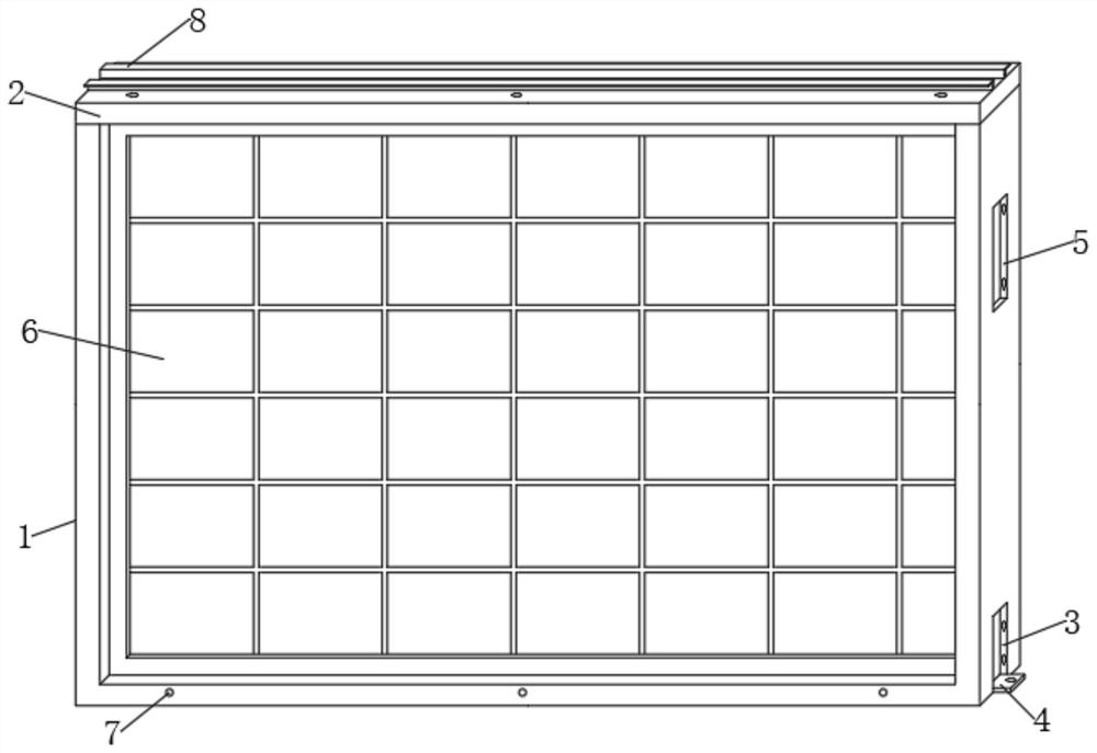
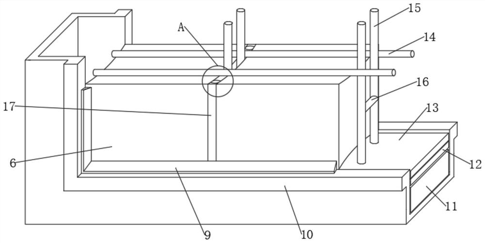
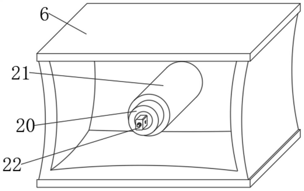
[0028] An embodiment of the present invention provides a combined glass block column partition structure, such as Figure 1-7 As shown, it includes a frame 1, a top frame 2 and an upper clamping groove 5. The upper end of the frame 1 is connected with the top frame 2 by bolts, and the upper clamping groove 5 is integrally stamped and formed on the outer side wall of the frame 1, and the lower end of the frame 1 is stamped integrally. Bottom clamping groove 3 is formed, the frame 1 at the lower side of the bottom clamping groove 3 is welded with a fixed angle plate 4, and an upper clamping block 24 is welded on the outer side wall of the frame 1 and the upper clamping groove 5 on the symmetrical side. The lower side of the solid block 24 is provided with a bottom card solid block 23, and the lower side of the frame 1 is integrally stamped with the fixed corner plate 4 to form a corner plate slot 25. The inner side is equidistantly provided with glass bricks 6, and the center of...


PUM


Abstract

The invention provides a combined glass brick cylinder partition structure, and relates to the field of glass brick cylinders. The combined glass brick cylinder partition structure comprises a side frame, a top frame and an upper clamping and fixing groove, the upper end of the side frame is connected with the top frame through bolts, the upper clamping and fixing groove is integrally punched andformed in one side wall of the outer portion of the side frame, a bottom clamping and fixing groove is integrally punched and formed in the lower end of the side frame, a fixing angle plate is weldedto the position, on the lower side of the bottom clamping and fixing groove, of the side frame, an upper clamping and fixing block is welded to the outer side wall of the side, symmetrical to the upper clamping and fixing groove, of the side frame, and a bottom clamping and fixing block is arranged on the lower side of the upper clamping and fixing block. Through the arrangement of the upper clamping and fixing groove, the bottom clamping and fixing groove, the fixing angle plate, the upper clamping and fixing block, the bottom clamping and fixing block, an angle plate inserting groove and theside frame, when the combined type glass brick cylinder partition structure is used, the outer side frames are clamped and fixed through the upper clamping and fixing block, the upper clamping and fixing groove, the bottom clamping and fixing block and the bottom clamping and fixing groove, then transverse bolts penetrate through the outer side frames, the connecting steps are simplified, and combination and installation are facilitated.

Description

technical field [0001] The invention relates to the field of glass brick columns, in particular to a combined glass brick column partition structure. Background technique [0002] Glass bricks are block-shaped or hollow box-shaped glass products that are formed by pressing transparent or colored glass frit. Its varieties mainly include glass hollow bricks and glass solid bricks, mosaics are not included. In most cases, glass bricks are not used as decorative materials, but as structural materials, used for walls, screens, partitions and other similar functions. The combined glass brick column partition can play a good partition role, and at the same time has a certain light transmission and decorative effect, meeting the needs of high-end decoration. [0003] When the existing combined glass brick column partition structure is in use, the outer frames are fixed by welding, and the connection steps are cumbersome, which is not convenient for combined installation. At the sa...

Claims


Application Information

Patent Timeline
IPC IPC(8): E04B2/74E04B2/82E04B2/06E04B1/684E04B1/70E04C1/42E04C1/39F21V33/00
CPCE04B1/6812E04B1/703E04B2/06E04B2/7453E04B2/7455E04B2002/0295E04C1/39E04C1/42F21V33/006
Inventor 何志伟顾彬裴友杰姜海娟陈生冯余爽王刚沙磊
Owner GOLD MANTIS FINE DECORATION TECH SUZHOU CO LTD
Learn More