Printing device of printing equipment for intelligent manufacturing
A technology of printing equipment and printing devices, which is applied to the general parts of printing machinery, printing, printing machines, etc., can solve the problems of inconvenient operation, time-consuming and labor-intensive, and low efficiency, and achieve the effect of time-saving and labor-saving operation
- Summary
- Abstract
- Description
- Claims
- Application Information
AI Technical Summary
Problems solved by technology
Method used
Image
Examples
Embodiment 1
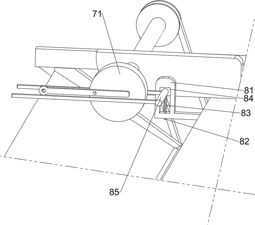
[0080] A printing device for intelligently manufactured printing equipment, such as figure 1 and figure 2 As shown, it includes a bed 1, a gear motor 2, a transmission assembly 3 and an embossing assembly 4; The output shaft of 2 is connected, and the inner side of the left part of the bed 1 is provided with a stamping assembly 4, and the stamping assembly 4 is connected with the transmission assembly 3.
[0081] Manual printing is time-consuming, labor-intensive, inefficient and inconvenient to operate. This device can automatically print products, saving time and effort, high in efficiency and convenient in operation. Inject ink into the embossing assembly 4, and then start the gear motor 2, the output shaft of the gear motor 2 rotates to drive the transmission assembly 3 to run, the transmission assembly 3 drives the embossing assembly 4 to run, and the embossing assembly 4 prints the product, and the product is completed After printing, people take out the product from ...
Embodiment 2
[0083] On the basis of Example 1, such as figure 2 , image 3 , Figure 4 and Figure 6 As shown, the transmission assembly 3 includes a first rotating shaft 31, a second rotating shaft 32, a first transmission device 33, a third rotating shaft 34, a second transmission device 35, a fourth rotating shaft 36 and a third transmission device 37, and the geared motor 2 A first rotating shaft 31 is arranged on the output shaft, and a second rotating shaft 32 is rotatably connected to the front and rear sides of the left side of the bed 1. The second rotating shaft 32 is connected to the embossing assembly 4, and the first rotating shaft 31 is connected to the front of the second rotating shaft 32. A first transmission device 33 is connected, and a third rotating shaft 34 is connected to the front and rear sides of the lower side of the right side of the bed in a rotational manner. 1. A fourth shaft 36 is provided on the upper right side to rotate, and the front part of the four...
Embodiment 3
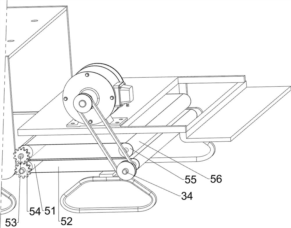
[0088] On the basis of Example 2, such as figure 1 , Figure 4 , Figure 5 , Figure 6 and Figure 7 As shown, a feeding assembly 5 is also included. The bed 1 is provided with a feeding assembly 5. The feeding assembly 5 is connected to the third rotating shaft 34. The feeding assembly 5 includes a first roller 51, a first conveyor belt 52, a fifth rotating shaft 53, The gear set 54, the second roller 55 and the second conveyor belt 56, three fifth rotating shafts 53 are rotationally connected to the front and rear sides of the bed 1, and the front part of the fifth rotating shaft 53 on the lower left side is provided with a gear set 54, and the gear set 54 It is connected to the front of the fifth rotating shaft 53 on the upper left side, the fifth rotating shaft 53 on the lower side and the third rotating shaft 34 are provided with first rollers 51, and the first rollers 51 on the left and right sides are wound with first conveyor belts 52, the fifth rotating shaft 53 o...
PUM
 Abstract
Description
Claims
Application Information
 - R&D
- Intellectual Property
- Life Sciences
- Materials
- Tech Scout
- Unparalleled Data Quality
- Higher Quality Content
- 60% Fewer Hallucinations
Browse by: Latest US Patents, China's latest patents, Technical Efficacy Thesaurus, Application Domain, Technology Topic, Popular Technical Reports.
© 2025 PatSnap. All rights reserved.Legal|Privacy policy|Modern Slavery Act Transparency Statement|Sitemap|About US| Contact US: help@patsnap.com


