
Bearing material ring feeding and discharging device and using method thereof

A material ring and bearing technology, applied in the field of the bearing material ring loading and unloading device, can solve the problems of complex structure of the loading and unloading device, many mechanical actions, long loading and unloading time, etc., and achieves simple structure, less mechanical action, and short loading and unloading time. Effect

Pending Publication Date: 2021-01-29
WUXI MACHINETOOL
View PDF0 Cites 0 Cited by
  • Summary
  • Abstract
  • Description
  • Claims
  • Application Information

AI Technical Summary

Problems solved by technology

[0003] The invention provides a loading and unloading device for a bearing material ring and a use method thereof, which can solve the technical problems of the existing loading and unloading device with complex structure, many mechanical actions, and long loading and unloading time

Method used


Image

  • Bearing material ring feeding and discharging device and using method thereof
  • Bearing material ring feeding and discharging device and using method thereof
  • Bearing material ring feeding and discharging device and using method thereof

Examples


Embodiment Construction

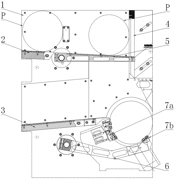
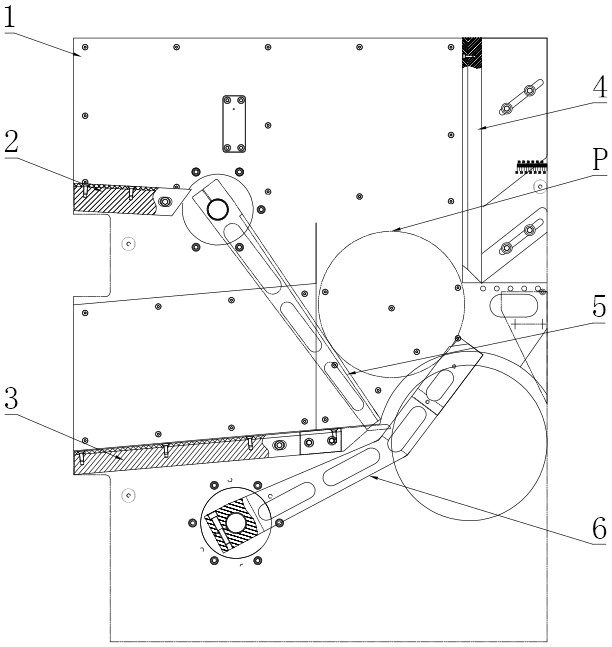
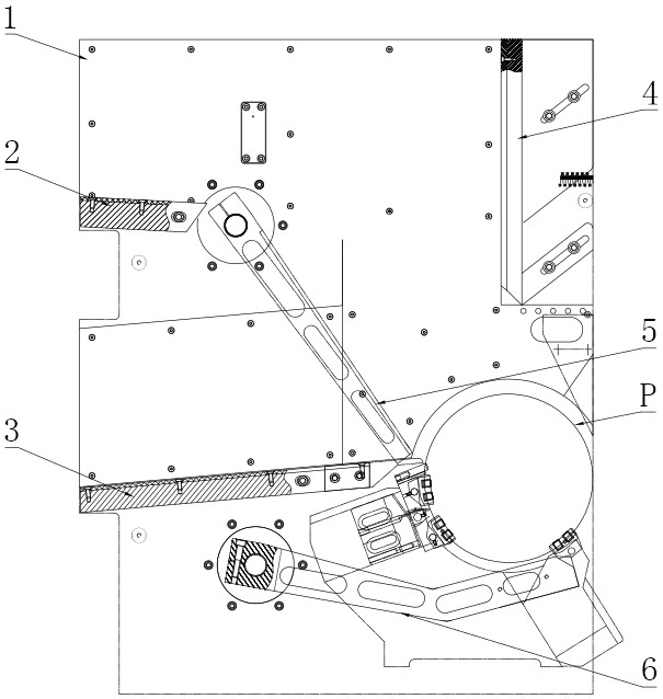
[0021] Such as figure 1 As shown, the loading and unloading device for the bearing material ring, wherein the bearing material ring P is an outer ring or an inner ring, and the device includes a front panel (not shown), a rear panel 1, a front panel and a rear panel 1 spaced apart from each other and arranged in parallel. The feed guide plate 2, the discharge guide plate 3, the transition guide plate 4, the material holder, and the upper rotating arm 5 and the lower rotating arm (not shown) are fixedly installed between them, and the feeding guide plate 2 faces downward to the right. Inclined setting, the discharge guide plate 3 is inclined to the lower left, so that the bearing material ring can roll down under the action of its own weight, the discharge guide plate 3 is located at the lower side of the feed guide plate 2, and the transition guide plate 4 is vertically arranged and located On the right side of the feed guide plate 2, the upper rotating arm 5 is located betwee...


PUM


Abstract

The invention provides a bearing material ring feeding and discharging device and a using method thereof. The technical problems that an existing feeding and discharging device is complex in structure, has a plurality of mechanical actions and is long in feeding and discharging time can be solved. The bearing material ring feeding and discharging device comprises a front panel and a rear panel which are arranged in parallel in a front-back spaced mode, wherein a feeding guide plate, a discharging guide plate, a transition guide plate, a material support, an upper rotating arm and a lower rotating arm are fixedly mounted between the front panel and the rear panel, and the upper rotating arm and the lower rotating arm are movably mounted between the front panel and the rear panel; the discharging guide plate is located on the lower side of the feeding guide plate, and the transition guide plate is vertically arranged and located on the right side of the feeding guide plate; the upper rotating arm is located between the feeding guide plate and the transition guide plate, and the left end of the upper rotating arm is adjacent to the right end of the feeding guide plate and connected with an upper driving unit; the upper driving unit drives the upper rotating arm to rotate, and the lower rotating arm is connected with a lower driving unit; and the lower driving unit drives the lowerrotating arm to rotate, and the material support is located below the right side of the discharging guide plate.

Description

technical field [0001] The invention relates to the technical field of processing auxiliary equipment for bearing outer rings and inner rings, in particular to a loading and unloading device for bearing material rings and a use method thereof. Background technique [0002] The existing loading and unloading devices for the outer and inner rings of bearings mainly adopt a rotary structure, but the existing rotary loading and unloading structure needs to be equipped with multiple sets of oil cylinders / air cylinders, which not only has a complex structure and high cost, but also has many mechanical actions and takes a long time for loading and unloading. long. Contents of the invention [0003] The invention provides a loading and unloading device for a bearing material ring and a use method thereof, which can solve the technical problems of the existing loading and unloading device with complex structure, many mechanical actions, and long loading and unloading time. [0004...

Claims


Application Information

Patent Timeline
Patent Type & Authority Applications(China)
IPC IPC(8): B65G47/22B65G47/42B65G47/57B65G47/82B65G47/88
CPCB65G47/22B65G47/42B65G47/57B65G47/82B65G47/8815
Inventor 肖伟媛陈雷
Owner WUXI MACHINETOOL
Learn More