Movable new energy automobile charging pile

A technology for new energy vehicles and charging piles, applied in electric vehicle charging technology, electric vehicles, charging stations, etc., can solve the problems of no electric shock-proof structure and inability to move, and achieve the effect of improving practicability and ease of use

Inactive Publication Date: 2021-01-29
云南夏远新能源发展有限责任公司
View PDF0 Cites 3 Cited by
  • Summary
  • Abstract
  • Description
  • Claims
  • Application Information

AI Technical Summary

Problems solved by technology

[0004] The purpose of the present invention is to provide a movable new energy vehicle charging pile to solve the problem that most of the existing vehicle charging piles proposed in the above background technology cannot be moved and do not have an electric shock prevention structure

Method used


Image

  • Movable new energy automobile charging pile
  • Movable new energy automobile charging pile
  • Movable new energy automobile charging pile

Examples


Embodiment 1

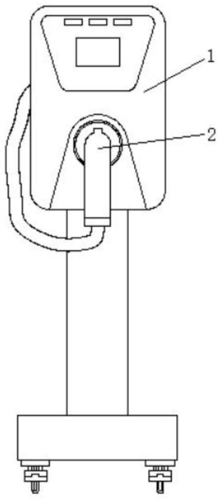
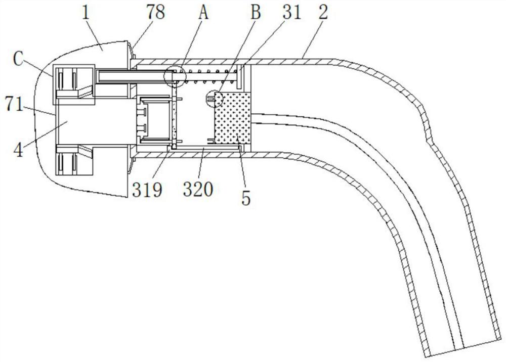
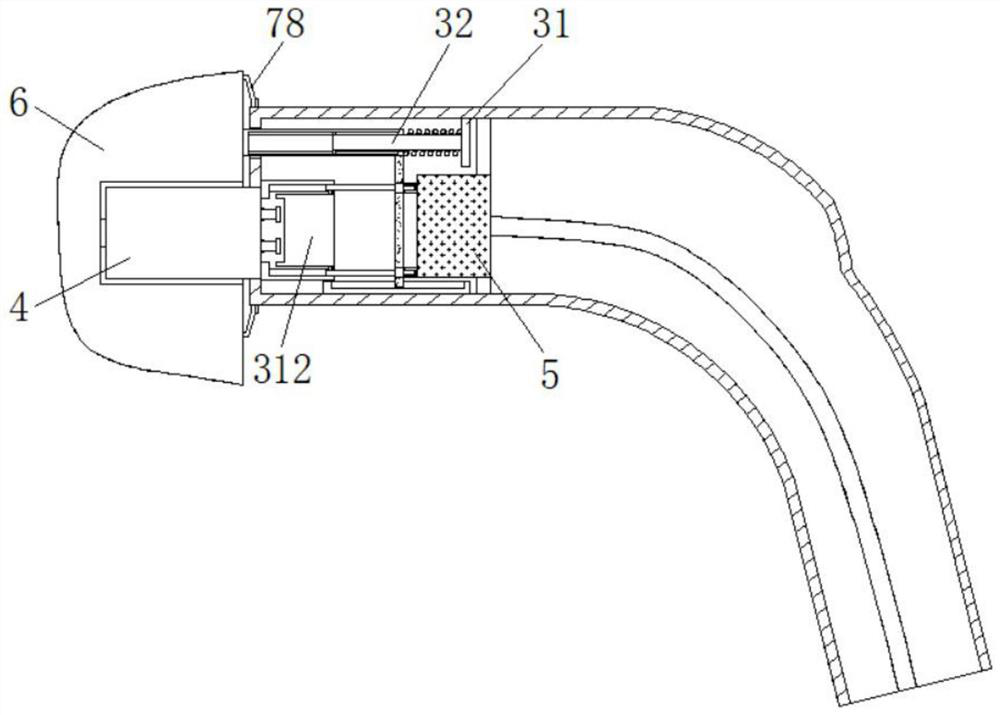
[0029] see figure 2 , 3, 4, 5, 7 and 8, the present invention provides a technical solution: including a device main body 1, a charging head 2, a charging sleeve 4, a conductive block 5 and a vehicle charging port 6, and a charging head 2 is inserted on the device main body 1 , the left side of the charging head 2 is provided with a charging sleeve 4, and the charging sleeve 4 is inserted into the inside of the device main body 1, the inside of the device main body 1 is provided with a fixing mechanism, and the inside of the charging head 2 is provided with an electric shock prevention mechanism to prevent The electric shock mechanism includes a fixed plate 31, a fixed rod 32, a first spring 33, a first slider 34, a first chute 35, a movable rod 36, a sliding plate 37, a conductive sheet 38, a movable slot 39, and a second slider 310 , second chute 311, fixed block 312, wire cavity 313, winding sleeve 314, rotating groove 315, conductive wire 316, conductive electrode 317, t...

Embodiment 2

[0032] see figure 2 , 3 And 6, the present invention provides a technical solution: the fixing mechanism includes a clamping cavity 71, a first set of rods 72, a cover rod groove 73, a second spring 74, a second set of rods 75, a clamping plate 76, and a clamping pad 77 And the suction cup 78, the charging sleeve 4 is inserted in the inside of the clamping cavity 71, and the clamping cavity 71 is set inside the device main body 1, and the two ends on the left side of the clamping cavity 71 are fixedly installed with the clamping cavity 71 and the second The inside of a cover rod 72 is provided with a cover rod groove 73, and the inside of the cover rod groove 73 is provided with a second spring 74, and the inside of the cover rod groove 73 is provided with a second cover rod 75, and the bottom of the second cover rod 75 The end is fixedly connected with the clamping plate 76, and the outside of the clamping plate 76 is provided with a clamping pad 77, and the left side of th...


PUM


Abstract

The invention relates to the technical field of automobile charging piles, in particular to a movable new energy automobile charging pile which comprises a device body, a charging head, a charging sleeve, a conductive block and an automobile charging port, the charging head is inserted into the device body, a fixing mechanism is arranged in the device body, and an anti-electric shock mechanism isarranged in the charging head; the anti-electric shock mechanism comprises a fixed plate, a fixed rod, a first spring, a first sliding block, a first sliding groove, a movable rod, a sliding plate, aconducting strip, a movable inserting groove, a second sliding block, a second sliding groove, a fixed block, a wire cavity, a winding sleeve, a rotating groove, a conducting wire, a conducting electrode, a torsional spring, a movable plate, a third sliding groove, a conducting inserting groove and a sleeve groove. The charging pile is advantaged in that problems that most of existing automobile charging piles cannot move and are not provided with anti-electric shock structures, and existing new energy automobile charging piles are loose in connection with charging heads and prone to falling off are solved.

Description

technical field [0001] The invention relates to the technical field of automobile charging piles, in particular to a movable new energy automobile charging pile. Background technique [0002] The function of the charging pile is similar to the fuel dispenser in the gas station. It can be fixed on the ground or wall, and installed in the parking lot or charging station of public buildings and residential areas. It can charge various types of electric vehicles according to different voltage levels. The charging pile The input end of the battery is directly connected to the AC power grid, and the output end is equipped with a charging plug for charging electric vehicles. Charging piles generally provide two charging methods: conventional charging and fast charging. It can be used by swiping the card on the computer interactive operation interface, and the corresponding charging method, charging time, cost data printing and other operations are performed. The display screen of t...

Claims


Application Information

Patent Timeline
IPC IPC(8): B60L53/31B60L53/16B60B33/00
CPCB60B33/00B60L53/16B60L53/31Y02T10/70Y02T10/7072Y02T90/12Y02T90/14
Inventor 不公告发明人
Owner 云南夏远新能源发展有限责任公司
Why Eureka
Try Eureka