
Air conditioning device for vehicle

A technology for air conditioning and vehicles, which is applied in air handling equipment, vehicle parts, transportation and packaging, etc. It can solve problems such as insignificant temperature changes, proportional distribution of cold and hot air, and slow cooling speed in the car, so as to improve the mixing efficiency , smooth flow and mixing, and the effect of reducing wind resistance

Active Publication Date: 2021-01-29
NANJING XIEZHONG AUTO AIRCONDITIONER CO CO LTD
View PDF6 Cites 0 Cited by
  • Summary
  • Abstract
  • Description
  • Claims
  • Application Information

AI Technical Summary

Problems solved by technology

The plate-type mixing damper of the existing air conditioner is at the position of 0%-30% and 70%-100%, and the problem of the proportion distribution of hot and cold air is more serious. At the position of 0%-30% and 70%-100%, the temperature of each air outlet Fast and slow, at the position of 30%-70%, the temperature change is not obvious
[0003] The existing air diversion mechanism in the mixing chamber cannot achieve uniform temperature difference of each air outlet when the mixing air door is in any position, resulting in that when the mixing air door is in different positions, the temperature difference of each air outlet varies from time to time, and the main driver and the co-driver The human body feels a large temperature difference, which is extremely uncomfortable; under the double blowing mode, it is impossible to realize the temperature stratification of the upper cold and the lower heat (the head is cold and the feet are hot) or the temperature difference between the upper and lower layers is too large (the head is too cold, the feet are too hot); the existing The air mixing mechanism is likely to cause heat leakage when it is fully cold, resulting in high outlet air temperature and slow cooling speed inside the car
[0004] The existence of the above phenomena makes it impossible to accurately calibrate the temperature controller in the car, and the calibrated controller is too hysteresis or sensitive to temperature fluctuations, causing extreme discomfort to the personnel

Method used


Image

  • Air conditioning device for vehicle
  • Air conditioning device for vehicle
  • Air conditioning device for vehicle

Examples


Embodiment Construction

[0042]The present invention will be more clearly and completely described below by way of a preferred embodiment with reference to the accompanying drawings, but the present invention is not limited to the scope of the described embodiment.

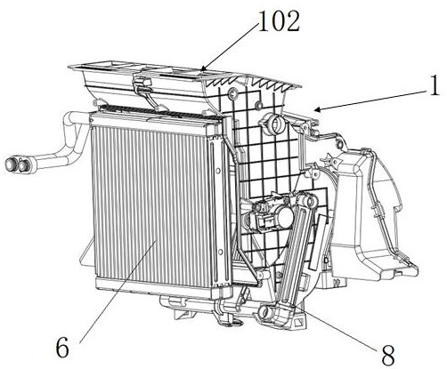
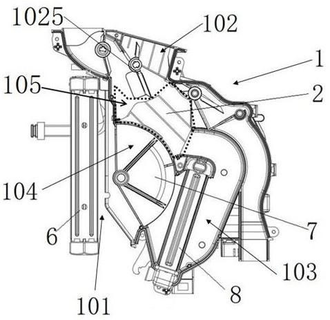
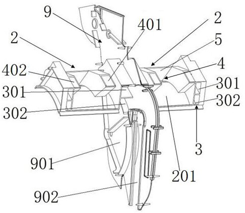
[0043] Such as figure 1 , figure 2 Shown is a vehicle air conditioning device provided by the present invention, including a distribution box 1 for air distribution in the vehicle. The distribution box 1 is a plastic structure with an inner cavity symmetrical to the left and right of the middle partition plate 9. The inner cavity is used for air circulation, and the housing of the distribution box 1 is provided with an air inlet 101 and an air outlet 102. The interior of the distribution box 1 is provided with a flow guide mechanism 2 for mixing hot and cold air and guiding the flow. Place the mixing chamber 105 of the flow guiding mechanism 2; hot air passages 3 are respectively set on both sides of the flow guiding mechanism 2, and a ...


PUM


Abstract

The invention discloses an air conditioning device for a vehicle, and belongs to the technical field of vehicle air conditioners. The device comprises a distribution box for distributing air in the vehicle, the distribution box comprises an air inlet and an air outlet, a flow guide mechanism for mixing cold air and hot air and guiding flow is arranged in the distribution box, and a mixed air dooris arranged at the air inlet of the distribution box. The flow guide mechanism is installed in the mixing cavity, the mixing cavity is located at the downstream junction of the hot air cavity and thecold air cavity, and all the air outlets communicate with the mixing cavity. Hot air channels are arranged on the two sides of the flow guide mechanism respectively, a cold air channel is arranged onthe inner side of each hot air channel, the hot air channel adopts a double-channel design, and a cold air inlet is formed in the lower-layer hot air channel. By means of the design of the mixed air door and the flow guide mechanism, calibration of temperature linearity and air volume distribution tests is facilitated, temperature control is more linear and accurate, the uniformity of the air outlet temperature is improved, meanwhile, temperature layering of upper cooling and lower heating can be achieved according to human body requirements, and the comfort level is improved.

Description

technical field [0001] The invention relates to the technical field of vehicle air conditioners, in particular to a vehicle air conditioner. Background technique [0002] Existing vehicle air-conditioning boxes generally adopt a two-box structure, and the main working principle is to supply air through the air supply section, distribute the ratio of hot and cold air through the plate-type mixing damper or sliding mixing damper, and then enter the distribution box. The hot and cold air are mixed in the mixing chamber, and the mixed air is sent to each air outlet. The plate-type mixing damper of the existing air conditioner is at the position of 0%-30% and 70%-100%, and the problem of the proportion distribution of hot and cold air is more serious. At the position of 0%-30% and 70%-100%, the temperature of each air outlet Fast and slow, at the 30%-70% position, the temperature change is not obvious. [0003] The existing air diversion mechanism in the mixing chamber cannot a...

Claims


Application Information

Patent Timeline
IPC IPC(8): B60H1/00
CPCB60H1/00664B60H1/00678B60H2001/00721
Inventor 孟德成余文峰唐栩王永王大健
Owner NANJING XIEZHONG AUTO AIRCONDITIONER CO CO LTD
Learn More