
Automatic pouring device with adjustable flow speed for sand casting

A technology of automatic pouring and sand casting, which is applied in the control of molten metal pouring from ladles, casting equipment, and equipment for transporting molds, etc. It can solve the problems of difficult control of molten iron flow rate, lower pouring efficiency, and lower pouring quality. Achieve the effects of improving pouring efficiency, reducing workload and improving safety

Inactive Publication Date: 2021-01-29
福州经济技术开发区星络网电子科技有限公司
View PDF0 Cites 1 Cited by
  • Summary
  • Abstract
  • Description
  • Claims
  • Application Information

AI Technical Summary

Problems solved by technology

[0002] In sand casting, molten iron needs to be poured into the sand mold box. The existing pouring method is generally to manually turn over the molten iron bucket and pour the molten iron into the pouring port. The manual pouring method is time-consuming and laborious, which reduces the pouring efficiency, and it is easy to cause safety accidents due to the lack of protective facilities. , in addition, the flow rate of molten iron is not easy to control in the way of manual pouring, and the flow rates required by different pouring stages and different types of castings are not the same, thus reducing the pouring quality

Method used


Image

  • Automatic pouring device with adjustable flow speed for sand casting
  • Automatic pouring device with adjustable flow speed for sand casting
  • Automatic pouring device with adjustable flow speed for sand casting

Examples


Embodiment Construction

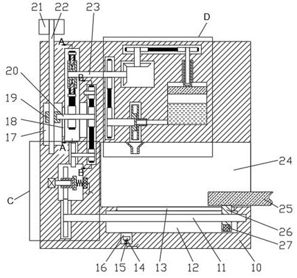
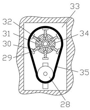
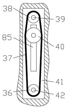
[0018] Combine below Figure 1-5 The present invention is described in detail, wherein, for the convenience of description, the orientations mentioned below are defined as follows: figure 1 The up, down, left, right, front and back directions of the projection relationship itself are the same.

[0019]An automatic pouring device with adjustable flow rate for sand casting described in conjunction with accompanying drawings 1-5 includes a main box body 10, and a pouring cavity 24 with an opening to the right is provided in the main box body 10, and the pouring cavity 24 The lower side is provided with a moving nut cavity 12, and a moving plate through cavity 13 is connected between the upper end wall of the moving nut cavity 12 and the lower end wall of the pouring cavity 24, and a screw gear cavity is provided on the left side of the moving nut cavity 12. 57, the upper end wall of the lead screw gear cavity 57 is connected with a conversion sleeve cavity 56, and the left end w...


PUM


Abstract

The invention relates to the related field of casting, and discloses an automatic pouring device with an adjustable flow speed for sand casting. The automatic pouring device comprises a main box body,a pouring cavity with a rightward opening is formed in the main box body, a movable nut cavity is formed in the lower side of the pouring cavity, and a movable plate through cavity is formed betweenthe upper end wall of the movable nut cavity and the lower end wall of the pouring cavity in a communicating manner. A lead screw gear cavity is formed in the left side of the movable nut cavity. Molten iron uniformly flows into a pouring opening of a sand mold box under the action of centrifugal force, automatic pouring is achieved, the workload of operators is reduced, the pouring efficiency isimproved, meanwhile, pouring is conducted in a mechanical mode, the safety during pouring can be improved, and the health of the operators is protected; and in addition, the pouring speed can be freely controlled through a molten iron flow speed adjusting mechanism, the requirement for different pouring speeds in different pouring stages is met, meanwhile, the pouring requirements of different sand mold boxes can be met, and the practicability of the device is improved.

Description

technical field [0001] The invention relates to the related field of casting, in particular to an automatic pouring device with adjustable flow rate for sand casting. Background technique [0002] In sand casting, molten iron needs to be poured into the sand mold box. The existing pouring method is generally to manually turn over the molten iron bucket and pour the molten iron into the pouring port. The manual pouring method is time-consuming and laborious, which reduces the pouring efficiency, and it is easy to cause safety accidents due to the lack of protective facilities. , In addition, the flow rate of molten iron is not easy to control in the way of manual pouring, and the flow rates required by different pouring stages and different types of castings are not the same, thus reducing the pouring quality. Contents of the invention [0003] The object of the present invention is to provide an automatic pouring device with adjustable flow rate for sand casting, which can...

Claims


Application Information

Patent Timeline
Patent Type & Authority Applications(China)
IPC IPC(8): B22D33/02B22D35/04B22D37/00
CPCB22D33/02B22D35/04B22D37/00
Inventor 朱俐一
Owner 福州经济技术开发区星络网电子科技有限公司
Learn More