
Video coding method, device and equipment and storage medium

A video coding and coding technology, applied in the field of video coding, can solve the problems of increasing video transmission coding overhead, large computational burden, and long coding time, and achieve the effects of reducing coding complexity, accurate coding, and improving efficiency

Inactive Publication Date: 2021-01-26
GUANGZHOU NETSTAR INFORMATION TECH CO LTD
View PDF0 Cites 6 Cited by
  • Summary
  • Abstract
  • Description
  • Claims
  • Application Information

AI Technical Summary

Problems solved by technology

In order to adapt to the bandwidth and equipment conditions of different transmission users, the source video will be encoded at the corresponding bit rate. In the existing video encoding, the higher the encoding complexity, the better the encoding quality, but the encoding is time-consuming. It will also be longer, and the long encoding time will cause the user to freeze when playing the video. Therefore, on the basis of ensuring high-quality encoding, it is also necessary to increase the encoding speed to reduce the encoding time during video transmission.
[0003] At present, most of the existing fast video coding methods are based on the transformation of the encoder itself. From frame-level coding to block coding, under the influence of the expected network bandwidth, a large number of recursive algorithms used in the coding decision-making part are continuously used to analyze the quality of each video frame. Image complexity, and then calculate the encoding rate used by each encoding block in the video frame; at this time, it is necessary to calculate the encoding cost of each encoding block at each recursive depth by analyzing the image complexity, resulting in a large amount of calculation burden and increasing the video Encoding overhead during transmission

Method used


Image

  • Video coding method, device and equipment and storage medium
  • Video coding method, device and equipment and storage medium
  • Video coding method, device and equipment and storage medium

Examples


Embodiment 1

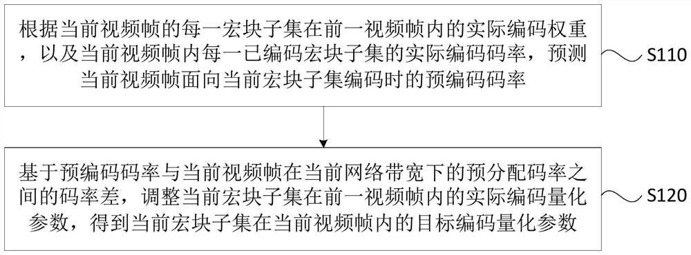
[0028] Figure 1A It is a flow chart of a video encoding method provided by Embodiment 1 of the present invention, and this embodiment is applicable to scenarios where there is a transmission requirement for any video. The video coding method provided in this embodiment can be executed by the video coding device provided in the embodiment of the present invention, and the device can be realized by means of software and / or hardware, and integrated in a computer device that executes the method, the computer A device may be a device participating in the interaction of video data.

[0029] Specifically, refer to Figure 1A , the method may include the following steps:

[0030] S110. According to the actual encoding weight of each macroblock subset of the current video frame in the previous video frame, and the actual encoding rate of each encoded macroblock subset in the current video frame, predict that the current video frame is oriented towards the current macroblock. The prec...

Embodiment 2

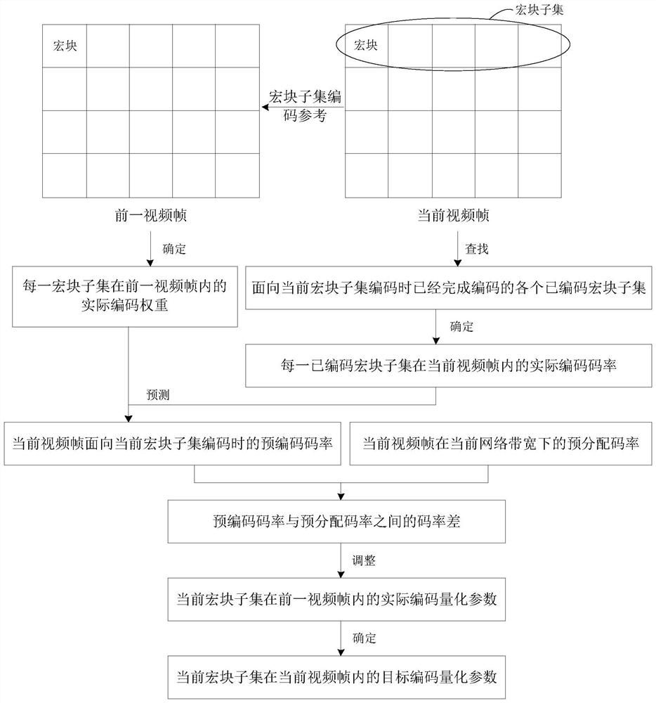
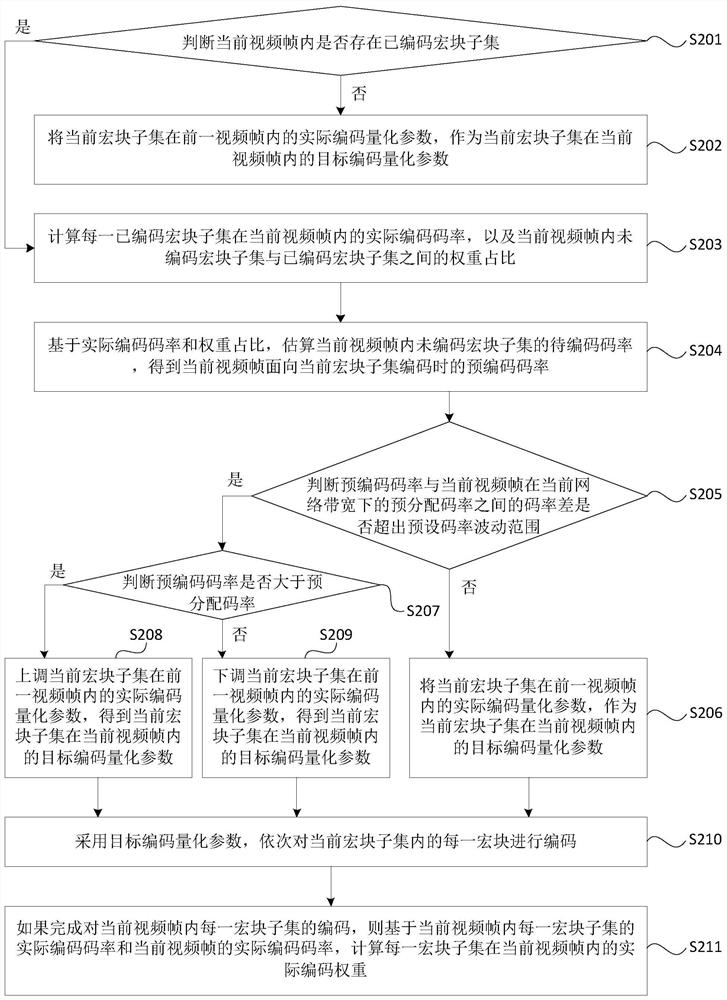
[0043] Figure 2A It is a flow chart of a video encoding method provided in Embodiment 2 of the present invention, Figure 2B It is a schematic diagram of the principles of the video encoding process provided by Embodiment 2 of the present invention. This embodiment is optimized on the basis of the foregoing embodiments. Specifically, such as Figure 2A As shown, this embodiment explains in detail the specific encoding process of sequentially encoding each macroblock subset in the current video frame.

[0044] optional, such as Figure 2A As shown, the following steps may be included in this embodiment:

[0045] S201. Determine whether a coded macroblock subset exists in the current video frame, if yes, perform S203; if not, perform S202.

[0046] Optionally, when encoding the current video frame in the video frame to be encoded, the current video frame will be divided into multiple macroblocks in advance, and the macroblocks will be combined to obtain multiple macroblock...

Embodiment 3

[0072] Figure 3A It is a flow chart of a video coding method provided by Embodiment 3 of the present invention, Figure 3B It is a schematic diagram of the principles of the video encoding process provided by Embodiment 3 of the present invention. This embodiment is optimized on the basis of the foregoing embodiments. Specifically, such as Figure 3A As shown, this embodiment explains in detail the specific implementation process of the frame loss policy in the video encoding process.

[0073] optional, such as Figure 3A As shown, the following steps may be included in this embodiment:

[0074] S310. Based on the pre-allocated bit rate of the current video frame under the current network bandwidth and the lower limit of the encoding bit rate of the associated video frame, estimate the amount of video pre-buffering during video transmission under the current network bandwidth.

[0075] Optionally, because if each video frame is encoded and transmitted, it may not be able...


PUM


Abstract

The embodiment of the invention discloses a video coding method and device, equipment and a storage medium. The method comprises the following steps: according to the actual coding weight of each macro block subset of a current video frame in a previous video frame and the actual coding rate of each coded macro block subset in the current video frame, predicting the pre-coding rate of the currentvideo frame for the coding of the current macro block subset; and based on the code rate difference between the pre-coding code rate and the pre-allocation code rate of the current video frame under the current network bandwidth, adjusting the actual coding quantization parameter of the current macro block subset in the previous video frame to obtain the target coding quantization parameter of thecurrent macro block subset in the current video frame. According to the technical scheme provided by the embodiment of the invention, the coding overhead and the coding complexity in the video codingprocess are greatly reduced, the high efficiency of video coding is improved, and the stability of the video coding quality is improved on the basis of ensuring that the network bandwidth fluctuationis met.

Description

technical field [0001] Embodiments of the present invention relate to the technical field of video transmission, and in particular, to a video coding method, device, device, and storage medium. Background technique [0002] With the rapid development of Internet technology and the increase of user demand for high-definition video, the amount of video data interacted with multimedia resources is also increasing. At this time, when video is transmitted, video compression and decoding technology is usually used to effectively extract video data. Redundant information enables fast transmission and offline storage of video data on the Internet. In order to adapt to the bandwidth and equipment conditions of different transmission users, the source video will be encoded at the corresponding bit rate. In the existing video encoding, the higher the encoding complexity, the better the encoding quality, but the encoding is time-consuming. It will also be longer, and too long encoding ...

Claims


Application Information

Patent Timeline
Patent Type & Authority Applications(China)
IPC IPC(8): H04N19/176H04N19/124H04N19/146
CPCH04N19/176H04N19/124H04N19/146H04N19/149H04N19/15H04N19/174H04N19/152
Inventor 包佳晶
Owner GUANGZHOU NETSTAR INFORMATION TECH CO LTD
Learn More