High-power laser automatic coupling device and coupling method

An automatic coupling and laser technology, applied in the coupling of optical waveguides, light guides, optics, etc., can solve the problems of difficult to guarantee yield, easy burning of optical fibers, complicated operation, etc., to avoid collision between optical fibers and lasers, and avoid direct large-scale The effect of coupling and improving coupling efficiency

Pending Publication Date: 2021-01-26
苏州格拉尼视觉科技有限公司
View PDF0 Cites 1 Cited by
  • Summary
  • Abstract
  • Description
  • Claims
  • Application Information

AI Technical Summary

Problems solved by technology

Traditional high-power lasers mostly use manual coupling, and the coupling of multiple current points often takes a lot of time, labor intensity is high, and the yield rate of coupling is difficult to guarantee
Secondly, when a high-power laser is coupled, if there is an error in the position of the fiber, the fiber is very easy to burn. Therefore, in the manual coupling method, when the position of the fiber is not controlled accurately, the proportion of fiber damage is relatively large
[0003] Some existing laser coupling devices on the market still have some disadvantages. First, the degree of automation is low, the structure is complex, the stability is low, and the later maintenance is frequent. Secondly, manual coupling, manual welding, and manual clamping of products are required, and the operation is complicated, resulting in long coupling time. , the processing efficiency is low, resulting in an increase in the production cost of the enterprise

Method used


Image

  • High-power laser automatic coupling device and coupling method
  • High-power laser automatic coupling device and coupling method
  • High-power laser automatic coupling device and coupling method

Examples


Embodiment Construction

[0048] The preferred implementation of the high-power laser automatic coupling device and method of the present invention will be further described in detail below with reference to the accompanying drawings.

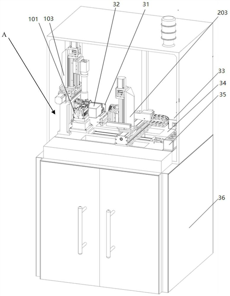
[0049] Such as Figure 1-2 as shown, figure 1 It is a perspective view of a high-power laser automatic coupling device in an embodiment of the present invention; figure 2 yes figure 1 The enlarged picture of part A in the middle, the coupling operation of the laser and the optical fiber is in figure 2 The automatic coupling device includes a laser assembly 10 and an optical fiber assembly 20, the laser assembly 10 includes a laser base 101, a laser single-axis rotation mechanism 105 is arranged on the laser base 101, and a laser single-axis rotation mechanism 105 is provided There is a laser box body 102, and one side of the laser base 101 is provided with a laser two-axis moving mechanism 103, and the laser two-axis moving mechanism 103 is provided with a vertical...


PUM


Abstract

The invention discloses a high-power laser automatic coupling device and a coupling method thereof. The automatic coupling device comprises a laser assembly and an optical fiber assembly, wherein thelaser assembly comprises a laser pedestal, a laser single-axis rotating mechanism, a laser double-axis moving mechanism, a vertical camera system, the optical fiber assembly comprises an optical fiberclamping mechanism for clamping an optical fiber, an optical fiber three-axis moving structure and a horizontal camera system, the vertical camera system shoots the position of a laser box body, thelaser single-axis rotating mechanism corrects the position of the laser box body to obtain the coupling position of the laser box body, and the horizontal camera system shoots the coupling position ofthe laser box body, and obtains the relative position of an optical fiber and the center of an optical fiber hole of the laser box body, the optical fiber three-axis moving mechanism adjusts the position of the optical fiber and inserts the optical fiber into the optical fiber hole, the optimal coupling position is determined based on preset coupling conditions, and the optical fiber three-axis moving mechanism drives the optical fiber to move to the optimal coupling position for coupling. The laser automatic coupling device and the coupling method thereof are high in coupling precision and high in coupling speed.

Description

technical field [0001] The invention relates to the technical field of automatic coupling and packaging, in particular to a high-power laser automatic coupling device and a coupling method. Background technique [0002] With the wide application of products such as laser cutting and high-speed optical modules, high-power lasers have been greatly developed. Traditional high-power lasers mostly use manual coupling. The coupling of multiple current points often takes a lot of time and labor intensity, and it is difficult to guarantee the yield of coupling. Secondly, when a high-power laser is coupled, if there is an error in the position of the fiber, the fiber is very easy to burn. Therefore, in the manual coupling method, when the position of the fiber is not controlled accurately, the proportion of fiber damage is relatively large. [0003] Some existing laser coupling devices on the market still have some disadvantages. First, the degree of automation is low, the structure...

Claims


Application Information

Patent Timeline
IPC IPC(8): G02B6/42
CPCG02B6/422G02B6/4225G02B6/4227G02B6/4296
Inventor 朱春雷
Owner 苏州格拉尼视觉科技有限公司
Why Eureka
Try Eureka