
Camera assembly and electronic equipment

A technology of camera components and camera modules, which can be applied to TVs, electrical components, color TVs, etc., can solve problems such as easy shaking, ball falling off, camera module position instability, etc., and achieve the effect of stable shooting and reduced shaking

Inactive Publication Date: 2021-01-22
OPPO CHONGQING INTELLIGENT TECH CO LTD
View PDF5 Cites 9 Cited by
  • Summary
  • Abstract
  • Description
  • Claims
  • Application Information

AI Technical Summary

Problems solved by technology

For different use states, the force on the ball structure and the anti-shake elastic is different. When the camera module and bracket are located under the ball structure and the anti-shake elastic, the camera module and bracket will pull the anti-shake elastic due to gravity. parts, resulting in insufficient pre-tightening force between the base and the bracket, which in turn causes the ball structure to fail to fit reliably with the base and bracket, and even causes the balls to fall off
As a result, the camera module cannot maintain a relative position relative to the casing in any state, which leads to unstable position of the camera module, easy shaking, and unstable shooting

Method used


Image

  • Camera assembly and electronic equipment
  • Camera assembly and electronic equipment
  • Camera assembly and electronic equipment

Examples


Embodiment Construction

[0028] Embodiments of the present application are described in detail below, examples of which are shown in the drawings, wherein the same or similar reference numerals denote the same or similar elements or elements having the same or similar functions throughout. The embodiments described below by referring to the figures are exemplary, and are only for explaining the present application, and should not be construed as limiting the present application.

[0029] The following describes the camera assembly 100 and the electronic device 1000 according to the embodiment of the present application with reference to the accompanying drawings.

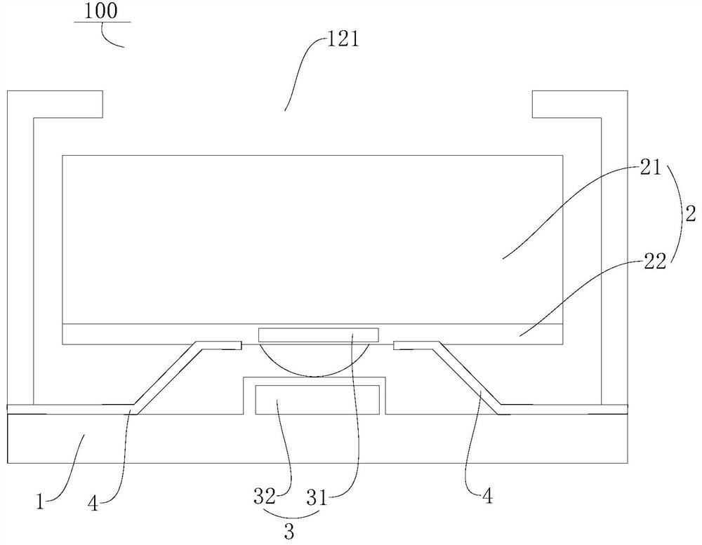
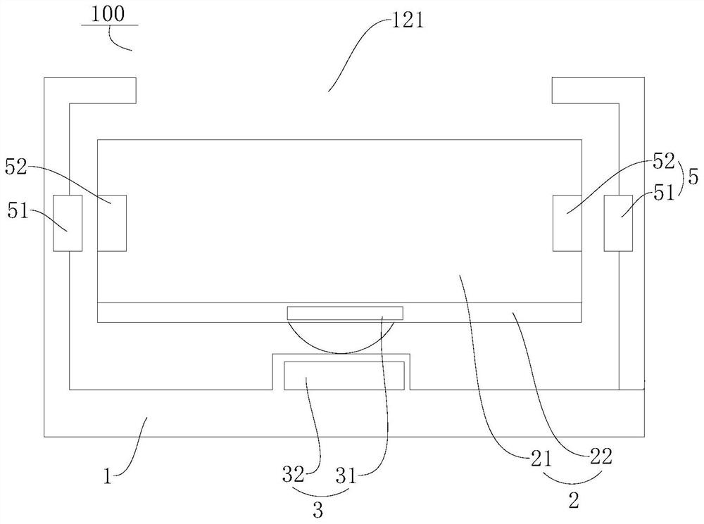
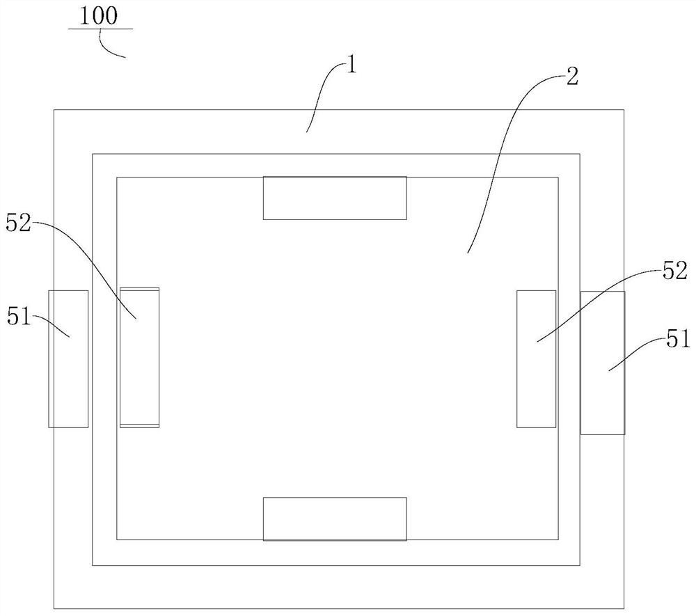
[0030] like Figure 1-Figure 2 As shown, the camera assembly 100 according to the embodiment of the present application includes a casing 1 , a movable part 2 and a first magnetic assembly 3 . Wherein, the movable part 2 is located in the casing 1 and is rotatable relative to the casing 1 , the movable part 2 includes a camera module 21 an...


PUM


Abstract

The invention discloses a camera assembly and electronic equipment. The camera assembly comprises a shell, a movable part and a first magnetic assembly, and a light through hole is formed in one sideof the shell; the movable part is located in the shell, the movable part comprises a camera module and a movable support, the movable support is arranged on the side, away from the light through hole,of the camera module, and the movable support is rotatably matched with the shell; and the first magnetic assembly comprises a first magnetic piece and a second magnetic piece, the first magnetic piece is arranged on the movable support, the second magnetic piece is arranged on the side wall of the side, opposite to the light through hole, of the shell, and the first magnetic piece and the secondmagnetic piece are magnetically attracted to ensure rotatable connection between the movable support and the shell. The camera assembly has the advantage of being stable in shooting.

Description

technical field [0001] The present application relates to the technical field of electronic equipment, in particular to a camera assembly and electronic equipment. Background technique [0002] In the field of electronic equipment technology, in order to realize the universal rotation of the camera module relative to the casing, generally a spherical ball structure and an anti-shake elastic member connecting the bracket and the base are arranged between the bracket and the base of the camera module. For different use states, the force on the ball structure and the anti-shake elastic is different. When the camera module and bracket are located under the ball structure and the anti-shake elastic, the camera module and bracket will pull the anti-shake elastic due to gravity. Parts, resulting in insufficient pre-tightening force between the base and the bracket, which in turn causes the ball structure to fail to fit reliably with the base and the bracket, and even causes the bal...

Claims


Application Information

Patent Timeline
Patent Type & Authority Applications(China)
IPC IPC(8): H04N5/225H04N5/232
CPCH04N23/50H04N23/57H04N23/685
Inventor 张弓
Owner OPPO CHONGQING INTELLIGENT TECH CO LTD
Learn More