
Novel magnetic coding motor

A magnetic encoding, a new type of technology, applied in the direction of electrical components, electromechanical devices, electric components, etc., can solve the problems of unfavorable productization, inconvenient threading, and increased costs

Pending Publication Date: 2021-01-22
苏州脉塔智能科技有限公司
View PDF0 Cites 0 Cited by
  • Summary
  • Abstract
  • Description
  • Claims
  • Application Information

AI Technical Summary

Problems solved by technology

[0003] In some specific occasions, when the output shaft is required to be hollow, the cable passes through the output shaft and passes through the gap between the magnetic encoder and the output shaft. However, when there are too many cables, due to the gap between the output shaft and the encoder Small size, threading is extremely inconvenient. In order to solve this problem, the method of passing the wire on the side and the method of side detection are generally adopted at present. The detection device is installed on the side of the rotating shaft in the side detection method, and is installed on the output shaft. The magnetic drum, and reserve a gap between the magnetic drum and the detection device to pass the line. The number of magnetic poles of the magnetic drum determines the resolution of the encoder, and the uniformity of the magnetic drum poles and the strength of the residual magnetism determine the output signal quality of the magnetic encoder. , has very high requirements in the manufacture and post-assembly of the magnetic drum, which greatly increases the cost and is not conducive to productization

Method used


Image

  • Novel magnetic coding motor

Examples


Embodiment Construction

[0013]In order to make the objectives, technical solutions and advantages of the present invention clearer, the following further describes the present invention in detail with reference to the accompanying drawings and embodiments. It should be understood that the specific embodiments described herein are only used to explain the present invention, but not to limit the present invention.

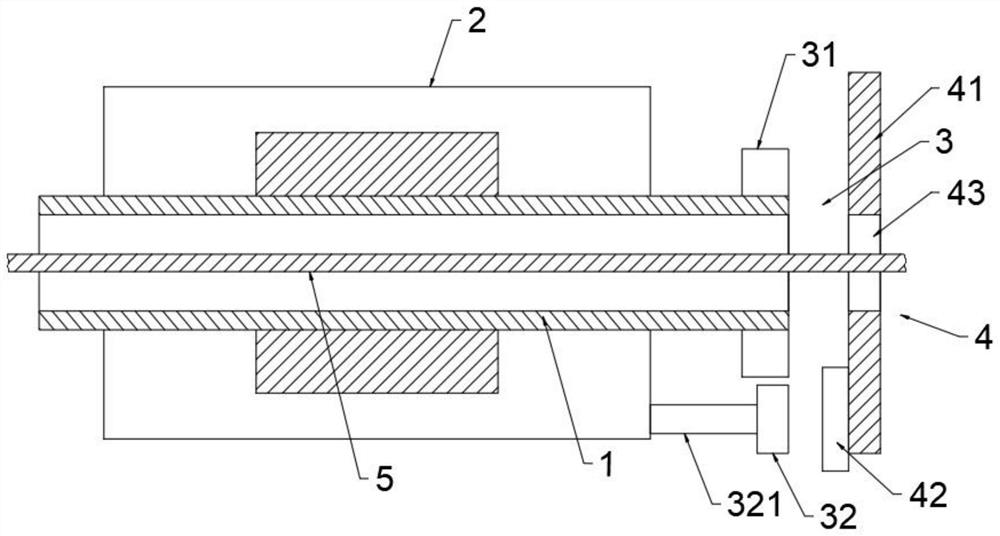
[0014]Such asfigure 1As shown, the present invention provides a new type of magnetic encoding motor, which includes an output shaft 1, a stator for driving the output shaft 1 to rotate, and a magnet mechanism for providing a detection magnetic field when the output shaft 1 rotates. 3. A detection mechanism 4 installed on the side of the magnet mechanism 3 away from the output shaft 1 for detecting the magnetic field change signal and a cable 5 connected with the detection mechanism 4 for transmitting the signal, so The output shaft 1 is a hollow cylindrical structure;

[0015]The magnet mechanism 3 inc...


PUM


Abstract

The invention provides a novel magnetic coding motor, and belongs to the field of motors. The magnetic coding motor comprises an output shaft, a stator used for driving the output shaft to rotate, a magnet mechanism rotating along with the output shaft and used for providing a detection magnetic field, a detection mechanism installed on the side, away from the output shaft, of the magnet mechanismand used for detecting magnetic field change signals, and a cable connected with the detection mechanism and used for transmitting signals, wherein the output shaft is of a hollow cylindrical structure, the magnet mechanism comprises a first magnet fixedly sleeving the outer surface wall of one end of the output shaft and a second magnet mounted on the stator and rotating along with the first magnet, and the detection mechanism comprises a control main board installed on the side, away from the output shaft, of the first magnet and a magnetic sensor installed at the position, corresponding tothe second magnet, of the control main board. The magnetic coding motor is simple in structure and convenient to use, and can effectively solve the problem that a traditional magnetic coding motor isinconvenient for wiring.

Description

Technical field[0001]The invention belongs to the technical field of motors, and particularly relates to a new type of magnetic encoding motor.Background technique[0002]With the development of science and technology, the application of magnetic encoders in motors is increasing. The magnetic encoder on the magnetic encoder motor uses the principle of giant reluctance to detect the magnet rotating with the shaft, and outputs position information through internal data processing. The use of magnetic coding requires the magnetic encoder to face the magnet that rotates with the motor shaft, and the distance between the two is basically concentrated in 2~5mm.[0003]In some specific occasions, when the output shaft is required to be hollow, the cable passes through the output shaft and passes through the gap between the magnetic encoder and the output shaft. However, when there are too many cables, the gap between the output shaft and the encoder It is small and inconvenient to thread. In o...

Claims


Application Information

Patent Timeline
IPC IPC(8): H02K11/215G01D5/12
CPCG01D5/12H02K11/215
Inventor 刘琼
Owner 苏州脉塔智能科技有限公司
Learn More