Water flow stabilizing valve and gas water heater applying same

A technology of steady flow valve and water flow, which is applied to fluid heaters, valve details, safety valves, etc., and can solve the problems of limited pressure range of steady flow, insufficient accuracy of steady flow, and inability of steady flow device to continue to play steady flow. , to achieve the effect of large steady flow range, avoiding water pressure increase, and strong adaptability

Active Publication Date: 2021-01-22
NINGBO FOTILE KITCHEN WARE CO LTD
View PDF14 Cites 0 Cited by
  • Summary
  • Abstract
  • Description
  • Claims
  • Application Information

AI Technical Summary

Problems solved by technology

[0004] However, this patent can only achieve one-stage steady flow through the movement of the valve core, and its steady flow pressure range is limited. If the pressure reaches the steady flow limit of the steady flow device, the valve core can no longer move, and the steady flow device cannot Continue to play the role of steady flow
[0005] In addition, because the lower seat (equivalent to the first plate below) can move relative to the outer casing (equivalent to the valve body below), there is a gap between the outer peripheral wall of the lower seat and the inner peripheral wall of the outer casing, so that water will flow from Flow through the gap between the outer peripheral wall of the lower seat and the inner peripheral wall of the housing will result in insufficient accuracy of steady flow

Method used


Image

  • Water flow stabilizing valve and gas water heater applying same
  • Water flow stabilizing valve and gas water heater applying same
  • Water flow stabilizing valve and gas water heater applying same

Examples


Embodiment Construction

[0044] The present invention will be further described in detail below in conjunction with the accompanying drawings and embodiments.

[0045] Such as Figure 13 As shown, the gas water heater in this preferred embodiment includes a heat exchanger 00, a water inlet pipe 01, a water outlet pipe 02, a water flow stabilization valve A and a water inlet joint 03, and the water inlet side of the heat exchanger 00 is connected to the water inlet pipe 01 , the water outlet side of the heat exchanger 00 communicates with the water outlet pipe 02 .

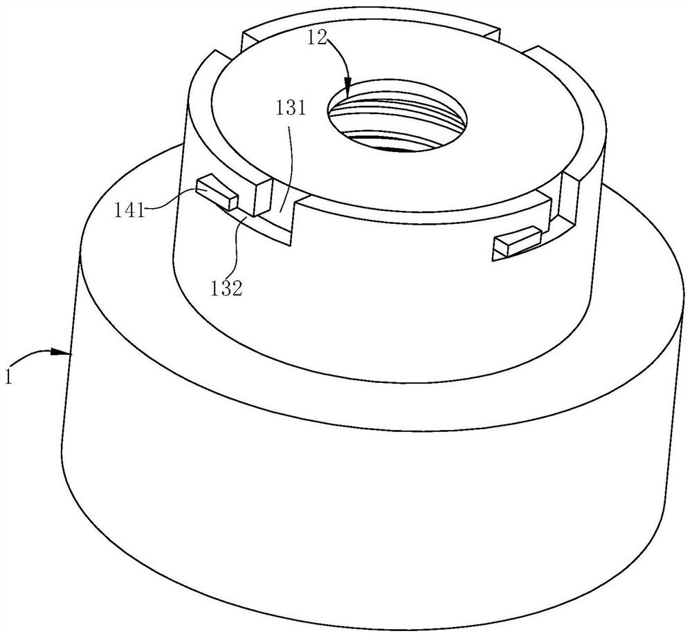
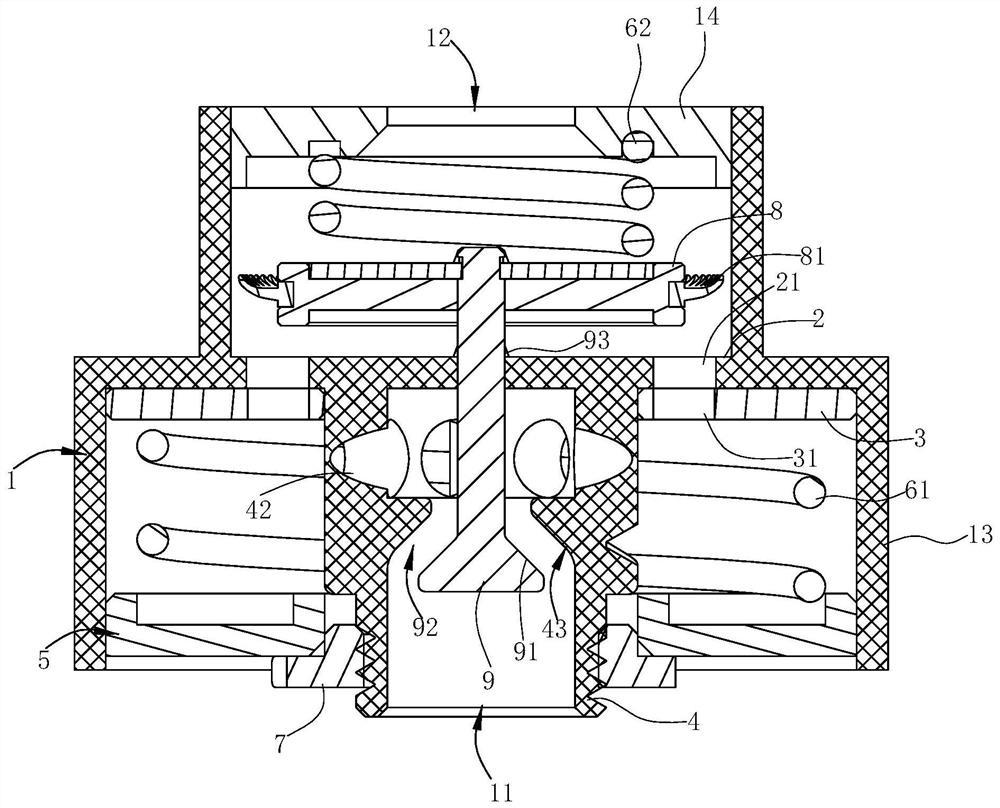
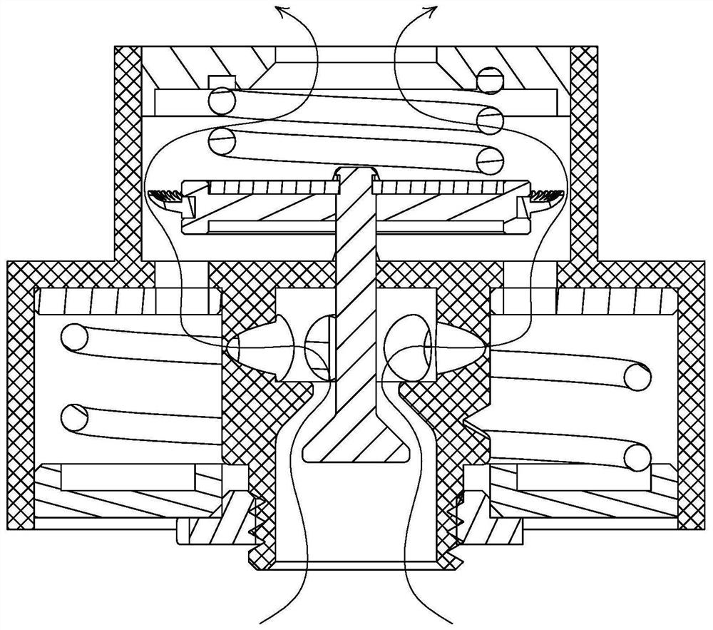
[0046] The water flow steady flow valve A includes a pipe body 1, a partition plate 2, an adjustment plate 3, a guide column 4, a first plate body 5, a second plate body 8, an adjustment rod 9, etc., and the lower end of the pipe body 1 is opened to form a water inlet. 11. There is a water outlet 12 on the top wall of the pipe body 1, the water inlet 11 on the pipe body 1 is in fluid communication with the water inlet joint 03, and the wa...


PUM


Abstract

The invention relates to a water flow stabilizing valve and a gas water heater applying the same. The water flow stabilizing valve comprises a pipe body, a partition plate, an adjusting plate, a guidecolumn, a first plate body and a first elastic piece. A water inlet is formed at the lower portion of the pipe body, and a water outlet is formed at the upper portion of the pipe body. The partitionplate is transversely arranged in the pipe body, and a water passing opening communicated with the water inlet and the water outlet is formed in the partition plate; the adjusting plate is located below the partition plate and attached to the partition plate, and a water passing hole capable of corresponding to or being staggered from the water passing opening is formed in the adjusting plate; theguide column is vertically arranged in the pipe body, and a guide groove spirally extending in the axial direction of the guide column is formed in the peripheral wall of the guide column; the firstplate body is located below the adjusting plate and fixedly connected with the adjusting plate, a guide block arranged in the guide groove is arranged on the first plate body, and the first plate bodycan move upwards relative to the guide column under the action of water flow; and the first elastic piece acts on the first plate body, so that the first plate body keeps a downward moving trend, anda flow stabilizing effect is achieved.

Description

technical field [0001] The invention relates to a flow stabilizing device, in particular to a water flow stabilizing valve and a gas water heater using the valve. Background technique [0002] Installing a water flow stabilization device in the gas water heater water system can effectively improve the temperature fluctuation of the hot water outlet caused by the fluctuation of the water flow, and improve the user's experience of using the gas water heater. 5.2.2.4.6 requirements in GB6932-2015 "Household Gas Instant Water Heater": The water system should be equipped with a flow stabilization or flow adjustment device. With the continuous increase of high-rise buildings, the water pressure of users' homes is becoming more and more complicated. In some communities, the water pressure is high and the water pressure fluctuates greatly, which brings certain troubles to the use of existing gas water heaters. The development of a convenient and adjustable flow stabilization device...

Claims


Application Information

Patent Timeline
IPC IPC(8): F16K17/30F16K17/34F16K27/02F16K27/04F24H9/00
CPCF16K17/30F16K17/34F16K27/02F16K27/045F24H9/0005
Inventor 王世平原世超茅忠群诸永定
Owner NINGBO FOTILE KITCHEN WARE CO LTD
Why Eureka
Try Eureka