Self-sealing oil discharge valve and hydraulic sealing method of oil discharge valve

A technology of hydraulic sealing and oil discharge valve, which is applied in the direction of engine sealing, lifting valve, valve device, etc. It can solve the problems of large leakage and easy jamming of the valve core, etc., and achieves reduced jamming, good sealing effect, and processing easy effect

Active Publication Date: 2021-12-07
重庆水泵厂有限责任公司
View PDF4 Cites 0 Cited by
  • Summary
  • Abstract
  • Description
  • Claims
  • Application Information

AI Technical Summary

Problems solved by technology

[0004] In view of the deficiencies of the above-mentioned technologies, the present invention provides a self-sealing oil discharge valve, which solves the technical problems of large leakage and easy jamming of the valve core

Method used


Image

  • Self-sealing oil discharge valve and hydraulic sealing method of oil discharge valve
  • Self-sealing oil discharge valve and hydraulic sealing method of oil discharge valve
  • Self-sealing oil discharge valve and hydraulic sealing method of oil discharge valve

Examples


Embodiment Construction

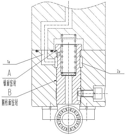
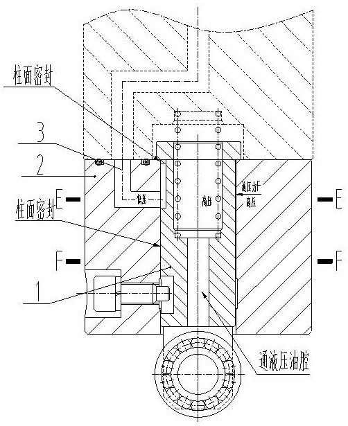
[0027] refer to figure 2 and image 3 As shown, a self-sealing oil discharge valve includes a spool and a valve body. The spool of the spool can slide along the spool hole in the valve body. A flange is provided on the end of the spool protruding from the spool hole. The flange is used to form a seal with the end face of the spool hole; the oil return hole in the valve body communicates with the spool hole, and the spool hole is a cylindrical hole; the spool is cylindrical, and the spool corresponds to the return hole. The position of the oil hole is provided with an overflow gap.

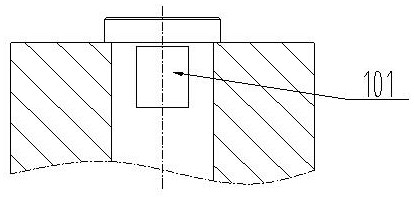
[0028] The overflow gap is a plane gap or a curved surface gap, and it is only necessary to ensure that part of the arc on the cylindrical surface of the valve column is removed. The chord length of the overcurrent notch refers to the chord length corresponding to the arc portion on the cylindrical surface of the valve post removed due to the processing of the overcurrent notch.

[0029] A sect...


PUM


Abstract

The invention discloses a self-sealing oil discharge valve and a hydraulic sealing method of the oil discharge valve, which solves the technical problems of large leakage and easy jamming of the valve core. Sliding against the spool hole in the valve body, the end of the spool protruding from the spool hole is provided with a flange, which is used to form a seal with the end face of the spool hole; the oil return hole in the valve body is in contact with the spool The hole is connected, and the valve column hole is a cylindrical hole; the valve column is cylindrical, and an overflow gap is provided on the valve column corresponding to the position of the oil return hole. The invention cleverly utilizes the pressure difference generated by oil leakage to automatically form a seal between the low-pressure side of the valve column and the valve column hole. The greater the pressure difference, the tighter the contact between the valve column and the valve column hole, and the better the sealing effect. The unfavorable situation in the prior art that the larger the gap is, the larger the leakage is completely reversed.

Description

technical field [0001] The invention relates to the technical field of oil discharge valve sealing. Background technique [0002] The oil drain valve is usually closed, refer to figure 1 As shown, the cone seal between the flange of the spool and the valve body, and the cylindrical surface must be sealed between the cylindrical surface of the spool and the inner hole of the valve body to prevent the oil in the high-pressure oil chamber from flowing under high pressure. The oil return hole is discharged. When there is too much oil, the spool of the oil discharge valve will be triggered by the guide rod and rise along the cylindrical hole in the valve body, thereby releasing the cone seal between the spool and the valve body, and the corresponding oil return hole on the valve body is equipped with The annular groove allows excess oil to flow into the oil return hole through the annular groove, and then be discharged from the oil return hole. [0003] Cylindrical sealing req...

Claims


Application Information

Patent Timeline
Patent Type & Authority Patents(China)
IPC IPC(8): F16K1/00F16J15/50
CPCF16J15/50F16K1/00
Inventor 管汝光刘祖清王升李文强霍开子
Owner 重庆水泵厂有限责任公司
Why Eureka
Try Eureka