Bushing, roller pin assembly and guide piston assembly

A technology of roller pins and bushings, which is applied in the direction of pump components, bearing components, engine components, etc., can solve the problem that the reliability, lubrication performance and service life of the guide piston components cannot adapt to the working conditions of the transmission parts, and the aggravation of the roller body and the bushing, etc. Roller pins and bushings are mechanically worn, and cannot meet the requirements of high-strength fuel injection pumps, etc., to achieve the effects of cooling effect, improved bearing capacity, simple structure, and high reliability

Inactive Publication Date: 2021-01-22
CHONGQING HONGJIANG MACHINERY
View PDF6 Cites 1 Cited by
  • Summary
  • Abstract
  • Description
  • Claims
  • Application Information

AI Technical Summary

Problems solved by technology

In order to meet the power, economy and emission requirements of modern new diesel engines, it is necessary to provide higher fuel injection pressure, which increases the load between the roller body of the guide piston assembly and the cam of the cam box, resulting in the roller body and the cam of the cam box. The contact stress between the bushing, the roller pin and the bushing increases, which intensifies the mechanical wear between the roller body and the bushing, the roller pin and the bushing, and severe abnormal wear will lead to damage or failure of the guide piston assembly, resulting in The entire fuel injection pump fails
In order for the pilot piston assembly to work normally, good lubrication must be provided, but there are many deficiencies in the structure of the conventional pilot piston assembly, resulting in the reliability, lubrication performance and service life of the conventional pilot piston assembly being unable to adapt to the increasing transmission components. The harsher working conditions cannot meet the requirements of high-strength fuel injection pumps, so it is necessary to improve the various parts of the pilot piston assembly

Method used


Image

  • Bushing, roller pin assembly and guide piston assembly
  • Bushing, roller pin assembly and guide piston assembly
  • Bushing, roller pin assembly and guide piston assembly

Examples


Embodiment Construction

[0028] The present invention will be described in detail below in conjunction with the accompanying drawings.

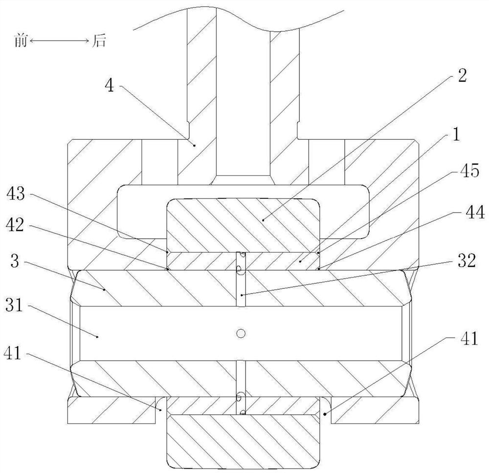
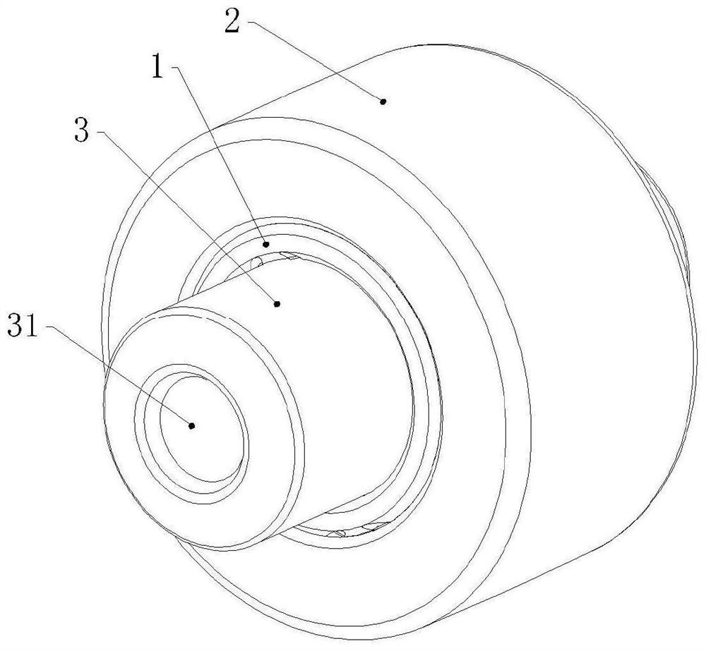
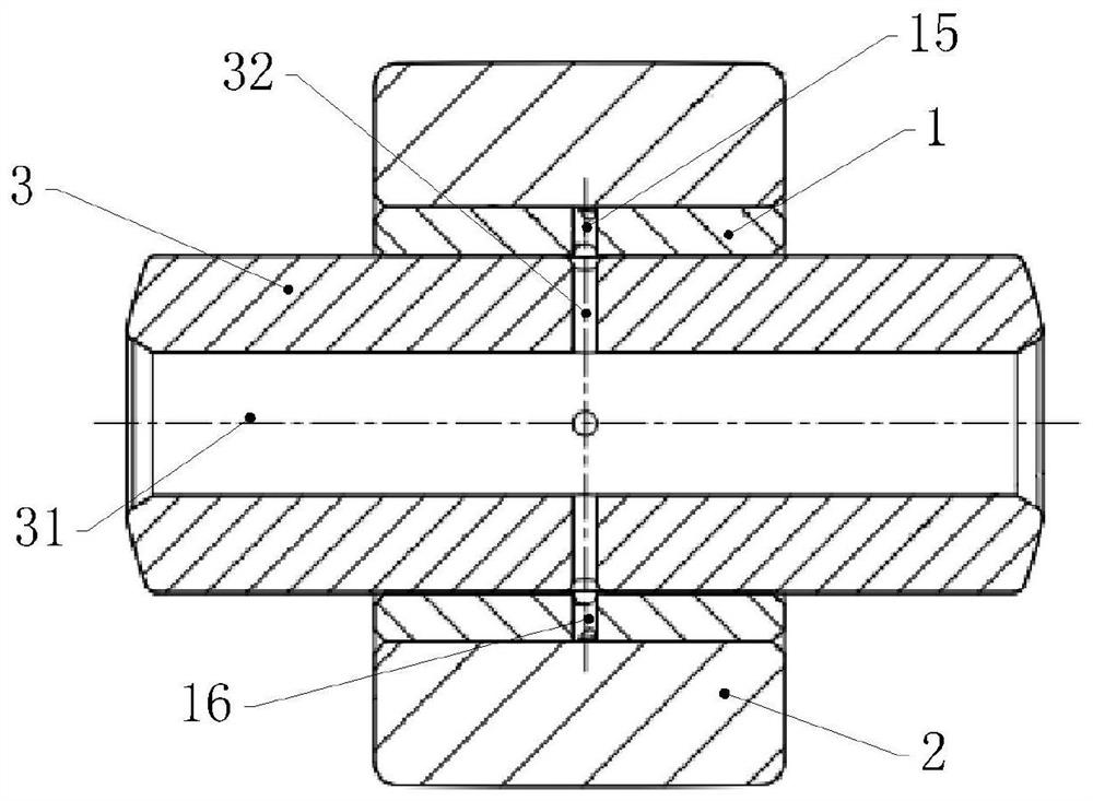
[0029] Such as Figure 4-Figure 10 As shown, a bushing in this embodiment includes a cylindrical bushing body 1, the inner wall of the bushing body 1 is provided with an inner lubricating oil groove, and the outer wall of the bushing body 1 is provided with The outer lubricating oil groove, the bushing body 1 is also provided with a lubricating oil hole for connecting the inner lubricating oil groove and the outer lubricating oil groove, the inner lubricating oil groove and the outer lubricating oil groove are both axially penetrated forward and backward groove.

[0030] In this embodiment, the inner lubricating oil groove includes a first inner helical lubricating oil groove 11 and a second inner helical lubricating oil groove 12, and the outer lubricating oil groove includes a first outer helical lubricating oil groove 13 and a second outer helical lubricating oil...


PUM


Abstract

The invention discloses a bushing, a roller pin assembly and a guide piston assembly, the bushing comprises a cylindrical bushing body, the inner wall of the bushing body is provided with an inner lubricating oil groove, and the outer wall of the bushing body is provided with an outer lubricating oil groove. A lubricating oil hole used for communicating the inner lubricating oil groove with the outer lubricating oil groove is further formed in the bushing body, and the inner lubricating oil groove and the outer lubricating oil groove are both grooves which are through front and back in the axial direction. The roller pin assembly and the guide piston assembly each comprise one bushing. The bushing, the roller pin assembly and the guide piston assembly provided by the invention have the advantages of being high in reliability, good in lubricating performance, long in service life, simple in structure and convenient to produce and machine.

Description

technical field [0001] The invention relates to the technical field of diesel engine accessories, in particular to a bushing, a roller pin assembly and a guide piston assembly. Background technique [0002] The guide piston assembly is an important component in the transmission part of the fuel injection pump, and its working condition has a direct impact on the quality of the fuel injection pump. In order to meet the power, economy and emission requirements of modern new diesel engines, it is necessary to provide higher fuel injection pressure, which increases the load between the roller body of the guide piston assembly and the cam of the cam box, resulting in the roller body and the cam of the cam box. The contact stress between the bushing, the roller pin and the bushing increases, which intensifies the mechanical wear between the roller body and the bushing, the roller pin and the bushing, and severe abnormal wear will lead to damage or failure of the guide piston assem...

Claims


Application Information

Patent Timeline
Patent Type & Authority Applications(China)
IPC IPC(8): F16C13/00F16C13/02F16C33/04F16N1/00F02M59/10F02M59/44F04B53/18
CPCF02M59/102F02M59/44F04B53/18F16C13/00F16C13/02F16C33/04F16N1/00
Inventor 周勇扈爽彭琦徐伟陈廷博龚元华田梦江欧金桃
Owner CHONGQING HONGJIANG MACHINERY
Why Eureka
Try Eureka