
Anti-impact offshore wind power generation equipment

A kind of wind power generation equipment and anti-shock technology, which is applied in the direction of wind power generation, wind power engine, wind power motor combination, etc., can solve the problems of wind power generator overall vibration, generator fan blade orientation deviation, etc., to improve wind energy conversion efficiency and airflow speed Large, precision-enhancing effects

Active Publication Date: 2021-01-22
SHANXI TIANBAO GRP CO LTD
View PDF20 Cites 0 Cited by
  • Summary
  • Abstract
  • Description
  • Claims
  • Application Information

AI Technical Summary

Problems solved by technology

Because the wind direction changes all the time, in the prior art, in order to pursue higher energy conversion efficiency, a wind vane or other sensing equipment is generally installed on the wind turbine to sense the wind direction, and then the orientation of the blades of the generator is controlled by the control equipment so that the wind can The fan blades are blown in the forward direction to obtain higher energy conversion efficiency. However, when the wind turbine is used at sea, the waves blown by the wind will continuously slap the support columns of the wind turbine, which will easily cause the overall vibration of the wind turbine, and eventually Affect the judgment of the wind direction sensing equipment, resulting in deviation of the orientation of the generator blades

Method used


Image

  • Anti-impact offshore wind power generation equipment
  • Anti-impact offshore wind power generation equipment
  • Anti-impact offshore wind power generation equipment

Examples


Embodiment 1

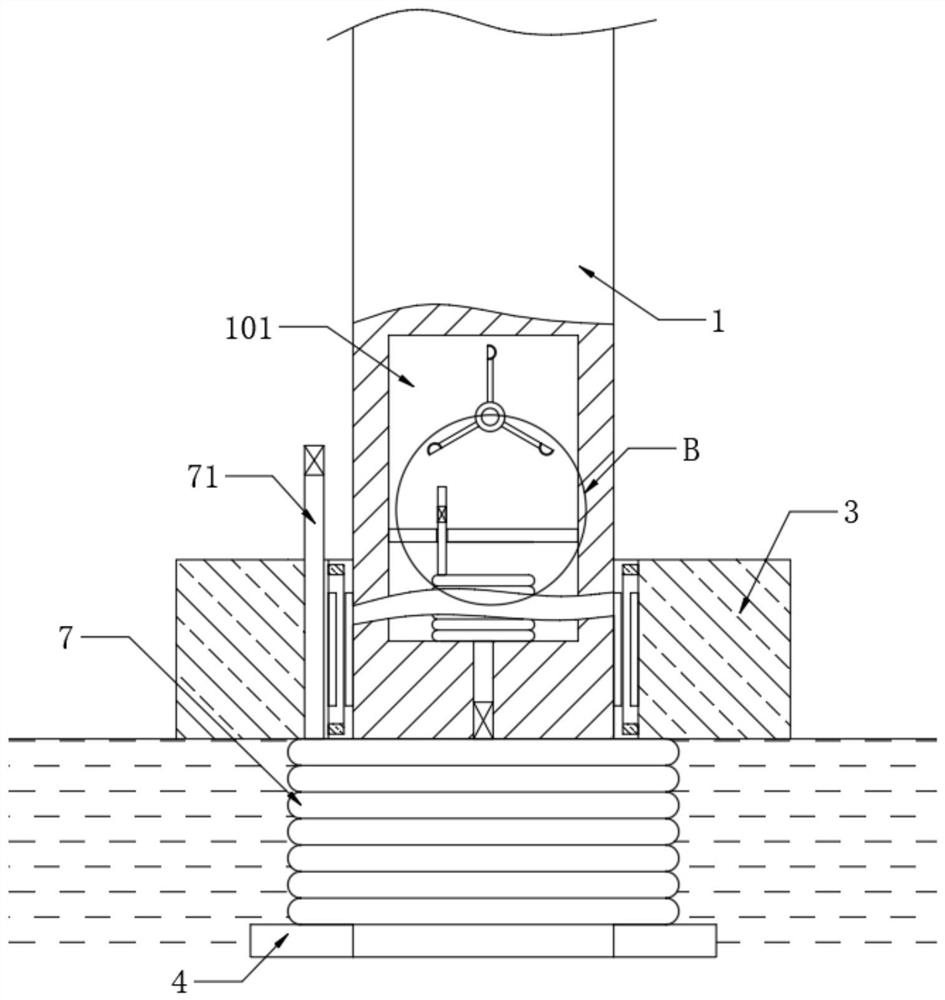
[0021] refer to Figure 1-2 , an anti-shock type offshore wind power generation equipment, including a support column 1, a wind power generation component is installed on the support column 1, and the wind power generation component is a power generation component in an existing wind power generation device, which has nothing to do with this scheme, so it will not be described in detail . The support column 1 is provided with buoys 3 outside. It should be noted that the height of the buoys 3 is relatively high, which can effectively prevent waves from passing over the buoys 3 and hitting the side wall of the support column 1 . The inner wall of the buoy 3 is fixedly connected with a plurality of first permanent magnets 5, and the side wall of the support column 1 is fixedly connected with a plurality of second permanent magnets 6 corresponding to the first permanent magnets 5, and the first permanent magnets 5 and The poles of the same name of the second permanent magnet 6 ar...

Embodiment 2

[0026] refer to Figure 3-4 The difference from the first embodiment is that the drive slot 101 is embedded with a partition 10, the bottom of the drive slot 101 is fixedly connected with the air bag 11, the one-way air outlet pipe 72 communicates with the inside of the air bag 11, and the air partition 10 is penetrated with a The exhaust pipe 2 communicated with the inside of the airbag 11 , and a pressure relief valve 21 is installed in the exhaust pipe 2 , and the outlet end of the exhaust pipe 2 faces the blade of the wind wheel 8 . It should be noted that, in this embodiment, due to the existence of the pressure relief valve 21, the exhaust pipe 2 exhausts air every once in a while and blows the wind wheel 8 to rotate, causing the wind wheel 8 to have a certain stop time, so Airbags 11 of different volumes can be installed in multiple groups of wind power generation equipment. When the air in the air bag 11 in a certain wind power generation equipment is exhausted and the...


PUM


Abstract

The invention discloses anti-impact offshore wind power generation equipment. The anti-impact offshore wind power generation equipment comprises a supporting column, a wind power generation assembly is installed on the supporting column, the supporting column is provided with a buoy in a sleeved mode, and a plurality of first permanent magnets are fixedly connected to the inner wall of the buoy; and a plurality of second permanent magnets corresponding to the first permanent magnets are fixedly connected to the side wall of the supporting column, the same-name magnetic poles of the first permanent magnets and the second permanent magnets are opposite, a plurality of metal rings corresponding to the second permanent magnets are fixedly connected to the inner wall of the buoy, a driving groove is formed in the side wall of the supporting column, and a wind wheel is rotationally connected into the driving groove. By arranging the buoy, the first permanent magnets, the second permanent magnets and other components, gushing waves can continuously beat the buoy, meanwhile, magnetic repulsion between the first permanent magnets and the second permanent magnets can overturn the buoy to impact the supporting column, so that vibration caused by the fact that the waves beat the supporting column is prevented, the accuracy of wind direction induction equipment is improved, and the wind power conversion efficiency is improved.

Description

technical field [0001] The invention relates to the technical field of wind power generation equipment, in particular to an anti-impact offshore wind power generation equipment. Background technique [0002] In the field of new energy applications, wind energy is a very clean and renewable energy, especially in the sea with frequent wind and waves, the wind energy is huge. Because the wind direction changes all the time, in the prior art, in order to pursue higher energy conversion efficiency, a wind vane or other sensing equipment is generally installed on the wind turbine to sense the wind direction, and then the orientation of the blades of the generator is controlled by the control equipment so that the wind can The fan blades are blown in the forward direction to obtain higher energy conversion efficiency. However, when the wind turbine is used at sea, the waves blown by the wind will continuously slap the support columns of the wind turbine, which will easily cause the...

Claims


Application Information

Patent Timeline
IPC IPC(8): F03D13/25F03D80/00F03D9/25
CPCF03D13/25F03D80/00F03D9/25Y02E10/72Y02E10/727
Inventor 潘铨
Owner SHANXI TIANBAO GRP CO LTD
Learn More