
A highway tunnel ventilation system and method with a combination of inclined shaft conveying and rowing and single horizontal passage

A technology for highway tunnels and ventilation systems, which is applied to mine/tunnel ventilation, earth-moving drilling, mining equipment, etc. The effect of reducing the investment in civil engineering and electromechanical engineering, reducing the energy consumption of ventilation operation, and shortening the length of smoke exhaust

Active Publication Date: 2021-11-09
中铁发展投资有限公司 +2
View PDF8 Cites 2 Cited by
  • Summary
  • Abstract
  • Description
  • Claims
  • Application Information

AI Technical Summary

Problems solved by technology

[0005] In a highway tunnel with a large longitudinal slope of about 10km in length, when the traffic volume is heavy, due to the influence of operating ventilation wind speed, energy consumption and fire smoke exhaust length, the uphill tunnel often adopts the combined ventilation method of two vertical / inclined shafts , the investment in ventilation civil engineering is large, the configuration of electromechanical system is complicated, and the energy consumption of operation is high
In these tunnels, the vertical / inclined shaft delivery and double-hole complementary ventilation method is adopted, which reduces the number of vertical / inclined shafts and reduces the investment in civil engineering. The ventilation system is complex, the configuration of mechanical and electrical equipment is still large, and the reduction in energy consumption is not obvious

Method used


Image

  • A highway tunnel ventilation system and method with a combination of inclined shaft conveying and rowing and single horizontal passage
  • A highway tunnel ventilation system and method with a combination of inclined shaft conveying and rowing and single horizontal passage
  • A highway tunnel ventilation system and method with a combination of inclined shaft conveying and rowing and single horizontal passage

Examples


Embodiment

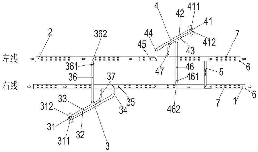
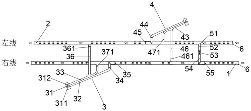
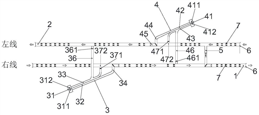
[0072] Such as figure 1 , figure 2 and image 3As shown, the present invention is a highway tunnel ventilation system combined with inclined shaft delivery and single transverse channel, including right line tunnel 1, left line tunnel 2, right line ventilation inclined shaft 3 and left line ventilation inclined shaft 4, right line ventilation The inclined shaft 3 is installed in the right-line tunnel 1, the left-line ventilation inclined shaft 4 is installed in the left-line tunnel 2, the right-line ventilation inclined shaft 3 is set opposite to the left-line ventilation inclined shaft 4; the right-line ventilation inclined shaft 3 includes the right-line inclined shaft Fan room 31, main air duct on the right line, air supply duct 34 at the bottom of the right line, exhaust duct 37 at the bottom of the right line, and flue exhaust duct 36 on the right line. The other end is respectively connected to the air supply duct 34 at the bottom of the right line, the exhaust duct 3...


PUM


Abstract

The invention discloses a highway tunnel ventilation system and method combined with an inclined shaft delivery and a single transverse channel. The inclined shaft and the left-line ventilation inclined shaft are set oppositely; the right-line ventilation inclined shaft includes the fan room of the right-line inclined shaft, the main air duct of the right line, the connecting air supply duct at the bottom of the right line, the connecting air exhaust duct at the bottom of the right line, and the smoke exhaust at the right line One end of the main air duct on the right line is connected to the inclined shaft fan room on the right line, and the other end is respectively connected to the air supply duct at the bottom of the right line, the exhaust duct at the bottom of the right line and the flue exhaust duct at the right line, and the air supply duct at the bottom of the right line and The exhaust duct at the bottom of the right line is connected to the tunnel on the right line, and the smoke exhaust duct on the right line is connected to the tunnel on the left line. Inclined shafts, as well as related contact air ducts, fan rooms and ventilation electromechanical facilities, reduce the investment in vertical / inclined shafts and ancillary civil engineering and electromechanical projects.

Description

technical field [0001] The invention relates to the technical field of ventilation for extra-long highway tunnels, in particular to a ventilation system and method for highway tunnels with a combination of inclined shaft conveying and rowing and single transverse passage. Background technique [0002] In the 1990s, a large number of expressway tunnels appeared in our country, and its ventilation mode has undergone a process of evolution from semi-horizontal to longitudinal. In 1990, through the investigation to Japan and the consultation and demonstration of Chinese and foreign experts, the full-jet longitudinal ventilation technology was applied to the downhill tunnel (3103m) of Zhongliang Mountain in Chengdu-Chongqing Expressway for the first time in China. Later, the Tanyugou Tunnel (3470m), Muyucao Tunnel (3610m), and Beibei Tunnel (4025m) adopted longitudinal ventilation. Nearly 30 years of operation have shown that this ventilation method is very successful, and the l...

Claims


Application Information

Patent Timeline
Patent Type & Authority Patents(China)
IPC IPC(8): E21F1/00
CPCE21F1/003
Inventor 付孝康孙永科蒋锋张子龙张晓君苏毅孙鹏张大强曾艳华
Owner 中铁发展投资有限公司
Learn More