
Low-wind-resistance car roof movable cover mounting structure

A technology of installation structure and wind resistance, applied in the direction of railway roof and other directions, can solve the problems of easy to cause water accumulation, difficult assembly, small drainage channel, etc., to solve the problem of water leakage, easy to manufacture and install, and simple installation structure.

Pending Publication Date: 2021-01-22
CRRC NANJING PUZHEN CO LTD
View PDF6 Cites 2 Cited by
  • Summary
  • Abstract
  • Description
  • Claims
  • Application Information

AI Technical Summary

Problems solved by technology

However, the movable roof structure of this structure is relatively complicated, and the "U" shape structure around the movable roof frame is difficult to manufacture, and the drainage channel is small, which is easy to cause water accumulation, and the water tank flap is prone to leaking when the rainfall is large.
There are 26 mounting points around the structure. Screws are used to cooperate with the threads. The manufacturing precision is high, and the assembly is difficult. Once the threads are corroded, it is not easy to maintain and replace.

Method used


Image

  • Low-wind-resistance car roof movable cover mounting structure
  • Low-wind-resistance car roof movable cover mounting structure
  • Low-wind-resistance car roof movable cover mounting structure

Examples


Embodiment Construction

[0026] Embodiments of the present invention will be explained below in conjunction with the accompanying drawings.

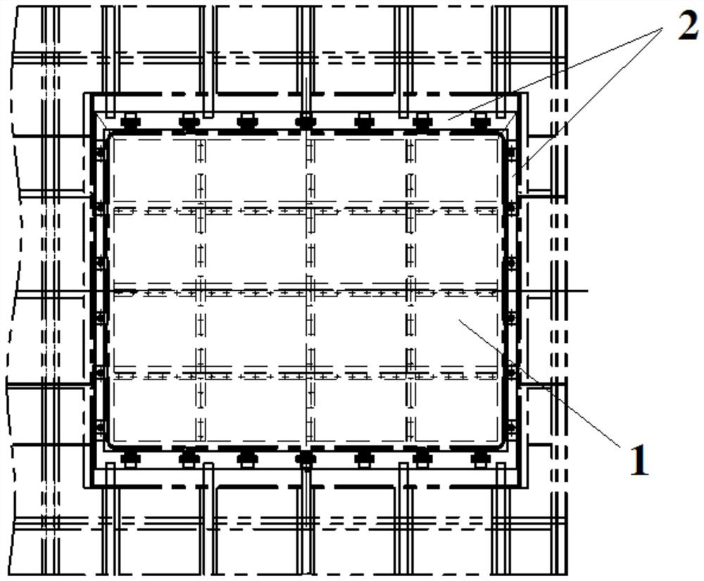
[0027] Such as Figures 1 to 10 As shown, the installation structure of the roof with low wind resistance in this embodiment mainly includes the roof installation frame 2 fixed on the roof and the roof cover 1 detachably installed and fixed on the roof installation frame 2, and the roof cover 1 The outer contour is consistent with the outer contour of the roof.

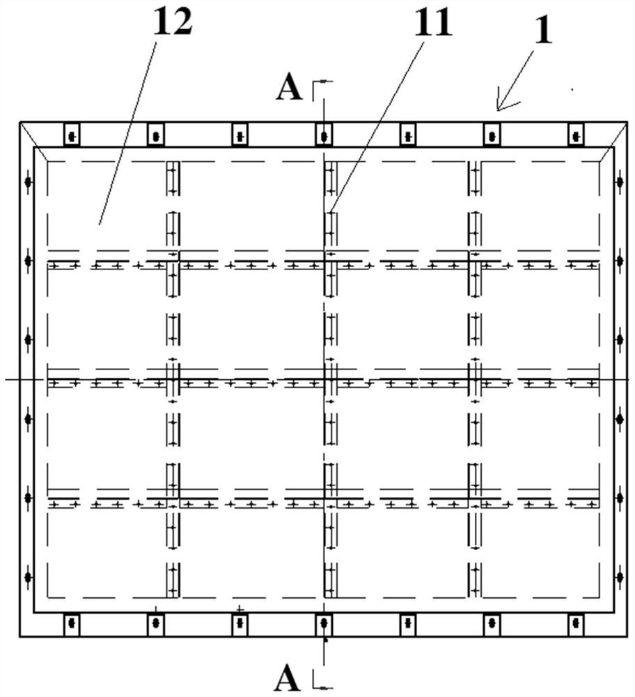
[0028] Such as figure 2 , image 3 As shown, the movable roof 1 has a steel frame 11 and a skin 12 fixed on the back of the steel frame 11 and cladding boards. The inner side of the steel frame 11 is provided with a heat insulating material 13, and the steel frame 11 is provided with the installation of the movable roof 1. hole. After the movable roof skin and the steel frame are welded, the heat insulation material is filled, and then the heat insulation material is covered with a thin steel plate...


PUM


Abstract

A low-wind-resistance car roof movable cover mounting structure comprises a movable top mounting frame fixed to a car roof and a movable top cover detachably installed and fixed to the movable top mounting frame, the outer contour of the movable top cover is consistent with the outer contour of the car roof, and the movable top mounting frame is provided with a transverse water collecting tank with the U-shaped section and a longitudinal beam with the L-shaped section. A plurality of mounting bolt seats are arranged in the transverse water collecting tank in the transverse direction of the vehicle, the longitudinal beam is provided with a bottom plate, an erected supporting edge located on the inner side of the bottom plate and a longitudinal C-shaped groove formed in the upper surface ofthe bottom plate, and a sliding block with a bolt is arranged in the C-shaped groove; the movable top cover is provided with mounting holes corresponding to the mounting bolt seats and the bolts in the C-shaped grooves respectively, the movable top cover and the movable top mounting frame are fixed through nuts, and a sealing rubber strip is further arranged between the movable top cover and the movable top mounting frame. The outer contour of the movable roof cover can be ensured to be consistent with the outer contour of the car roof, the installation structure is simple, manufacturing and installation are convenient, and meanwhile the problem of water leakage of the movable roof cover is solved.

Description

technical field [0001] The invention relates to a mounting structure for a movable roof cover of a rail vehicle. Background technique [0002] Rail vehicles often have some large equipment with a high degree of integration, which cannot be entered from the end door or side door, which requires a movable roof for hoisting equipment on the roof. As the design speed of rail vehicles is getting higher and higher, the design of the movable roof is required to be as smooth as possible in order to reduce running resistance and reduce running noise. [0003] Chinese utility model patent CN202243470U discloses a kind of installation structure of rail car roof water tank movable cover, and this movable roof installation structure is the structure that movable roof protrudes the roof profile, adopts the mode that pressing plate is pressed during installation and is installed. Its movable roof protrudes from the roof profile, and the installation method of pressing it with a pressure p...

Claims


Application Information

Patent Timeline
IPC IPC(8): B61D17/12
CPCB61D17/12Y02T30/00
Inventor 廖平朱亮王潇雨王小霞张晓珍
Owner CRRC NANJING PUZHEN CO LTD
Learn More