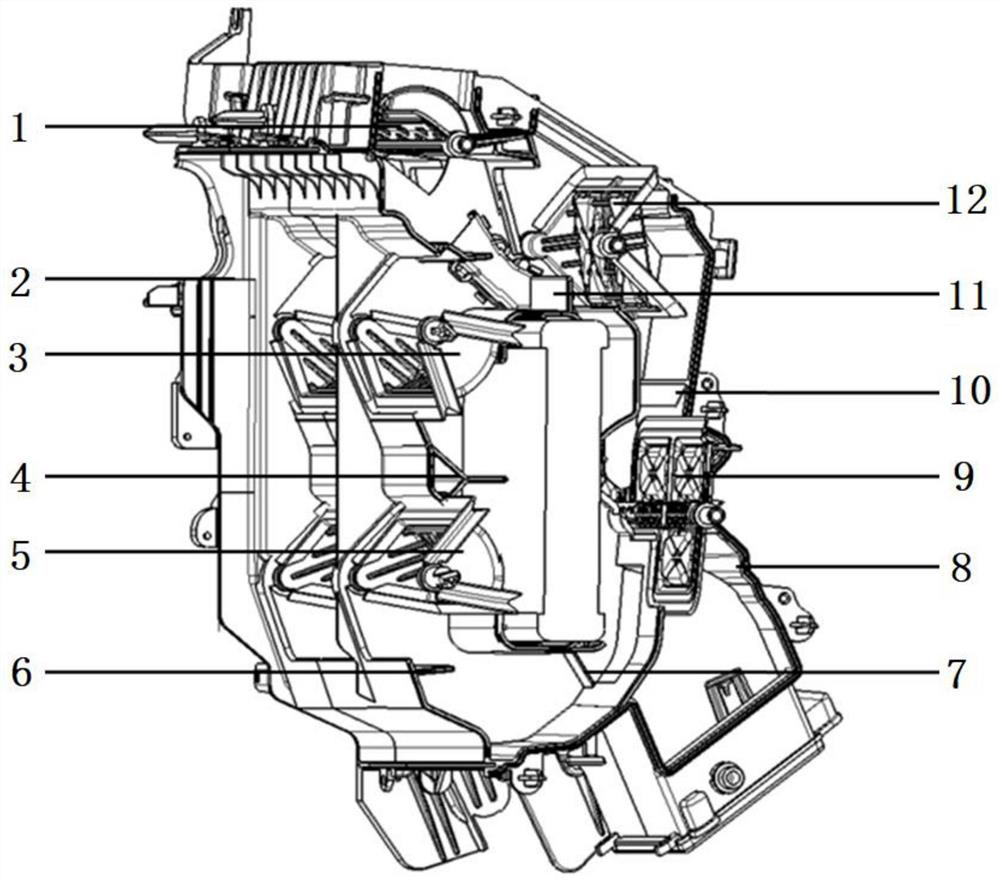
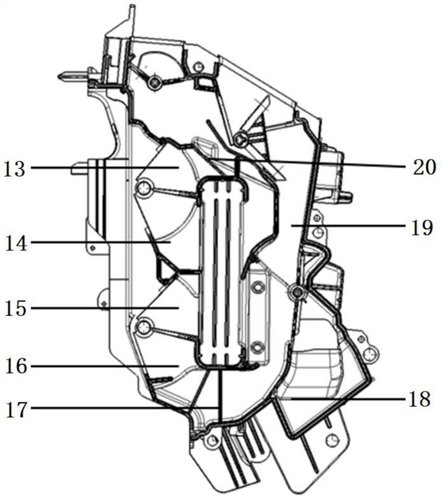
Automobile air conditioning system temperature control curve optimization structure

An automotive air-conditioning system and a technology for optimizing the structure, applied in vehicle components, air handling equipment, heating/cooling equipment, etc., can solve the problems that the temperature at the mixing position cannot be adjusted in layers, easily form vortices, and the temperature of the blowing surface is high. The difference between the defrosting temperature and the blowing surface temperature is large, the effect of preventing the upper layer of hot and cold air from colliding, and reducing the amount of cold air

Pending Publication Date: 2021-01-22
SOUTH AIR INT
View PDF0 Cites 0 Cited by
  • Summary
  • Abstract
  • Description
  • Claims
  • Application Information

AI Technical Summary

Problems solved by technology

[0002] In the traditional automobile air conditioning box technology, the cold and hot mixed air inside the air conditioning box can only be adjusted by the opening of the mixing damper. The structure is relatively limited, and the hot and cold air is easy to form a hedge and mix unevenly; , resulting in a large temperature difference between the upper and lower sides, and the air outlet on the blowing surface has less heat loss than the air outlet on the foot and the rear blowing surface, resulting in a higher temperature on the blowing surface than the foot and rear blowing surfaces; in different modes, the mixed air position is easy to form a vortex, convection The field has a great influence; when the air conditioner is in the foot blowing defrosting mode, the large temperature difference will easily cause low defogging and defrosting efficiency
Generally speaking, the comfort in the passenger compartment is not well controlled, and there are potential safety hazards for driving

Method used


Image

  • Automobile air conditioning system temperature control curve optimization structure
  • Automobile air conditioning system temperature control curve optimization structure

Examples


Embodiment Construction

[0021] Embodiments of the present invention are described below through specific examples, and those skilled in the art can easily understand other advantages and effects of the present invention from the content disclosed in this specification. The present invention can also be implemented or applied through other different specific implementation modes, and various modifications or changes can be made to the details in this specification based on different viewpoints and applications without departing from the spirit of the present invention. It should be noted that the diagrams provided in the following embodiments are only schematically illustrating the basic concept of the present invention, and the following embodiments and the features in the embodiments can be combined with each other in the case of no conflict.

[0022] Wherein, the accompanying drawings are for illustrative purposes only, and represent only schematic diagrams, rather than physical drawings, and should...


PUM


Abstract

The invention belongs to the field of automobiles, and relates to an automobile air conditioning system temperature control curve optimization structure which comprises a middle shell, a left shell and a right shell, and a face blowing air door, a foot blowing air door and a defrosting air door which are used for controlling face blowing, foot blowing and defrosting respectively are arranged in acavity formed by the middle shell, the left shell and the right shell. The structure further comprises an air mixing door which comprises an upper mixing air door and a lower mixing air door which areindependently arranged; the upper mixing air door comprises an upper-layer cold runner and an upper-layer hot runner, and the lower mixing air door comprises a lower-layer hot runner and a lower-layer cold runner. According to the invention, the linearity can be better optimized, the temperature can be orderly and quantitatively increased, the jittering condition is avoided, the temperature difference between the upper, lower, left, right, front and back parts can be better changed, the temperature difference required by different parts of passengers is effectively met, the comfort of a passenger compartment is better controlled, and vehicle models with more modes can be efficiently met.

Description

technical field [0001] The invention belongs to the field of automobile air conditioners, and relates to an optimization structure for temperature control curves of an automobile air conditioner system. Background technique [0002] In the traditional automobile air conditioning box technology, the cold and hot mixed air inside the air conditioning box can only be adjusted by the opening of the mixing damper. The structure is relatively limited, and the hot and cold air is easy to form a hedge and mix unevenly; , resulting in a large temperature difference between the upper and lower sides, and the air outlet on the blowing surface has less heat loss than the air outlet on the foot and the rear blowing surface, resulting in a higher temperature on the blowing surface than the foot and rear blowing surfaces; in different modes, the mixed air position is easy to form a vortex, convection The field has a great influence; when the air conditioner is in the foot blowing defrostin...

Claims


Application Information

Patent Timeline
Patent Type & Authority Applications(China)
IPC IPC(8): B60H1/00
CPCB60H1/00664B60H2001/00721
Inventor 李施彤吴贵超袁月张钊吴长发谢朝曹京城李磊宁向梅覃旗开
Owner SOUTH AIR INT
Why Eureka
Try Eureka