
Welding process platform with marking device

A scribing device and welding process technology, applied in welding equipment, auxiliary devices, auxiliary welding equipment, etc., can solve the problems of poor splicing accuracy, high labor intensity of operators, human body damage, etc., to ensure welding accuracy, splicing firm and reliable. , to ensure the effect of structural strength

Active Publication Date: 2021-01-22
NUCLEON XINXIANG CRANE
View PDF9 Cites 4 Cited by
  • Summary
  • Abstract
  • Description
  • Claims
  • Application Information

AI Technical Summary

Problems solved by technology

[0002] As is well known, currently in the manufacturing process of spliced ​​end beams of cranes, when assembling slotted end beams and connecting beams, due to the large size of the plates, the amount of deformation in the natural state is also large, and the operator usually needs manual assistance when splicing and assembling. The crowbar aligns the panels to the position line, resulting in high labor intensity for operators, low efficiency, and poor splicing accuracy. Most of the finished products after welding need to be corrected, and the operation steps are cumbersome; When the beam box is placed on the level ground, the operator is in a squatting or bending state for a long time, which will cause great damage to the human body. This phenomenon is an urgent problem to be solved by those skilled in the art;
[0003] Chinese patent (Notice No.: CN110369928A) discloses a method for assembling side-bearing frames. This patent splices frames on a welding platform so that the operator can operate upright and improves splicing accuracy to a certain extent. The patent applies to a single product and cannot be applied to products of different specifications

Method used


Image

  • Welding process platform with marking device
  • Welding process platform with marking device
  • Welding process platform with marking device

Examples


Embodiment Construction

[0029] The present invention can be explained in detail through the following examples, and the purpose of disclosing the present invention is to protect all technical improvements within the scope of the present invention.

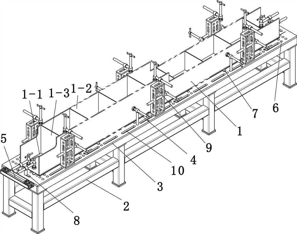
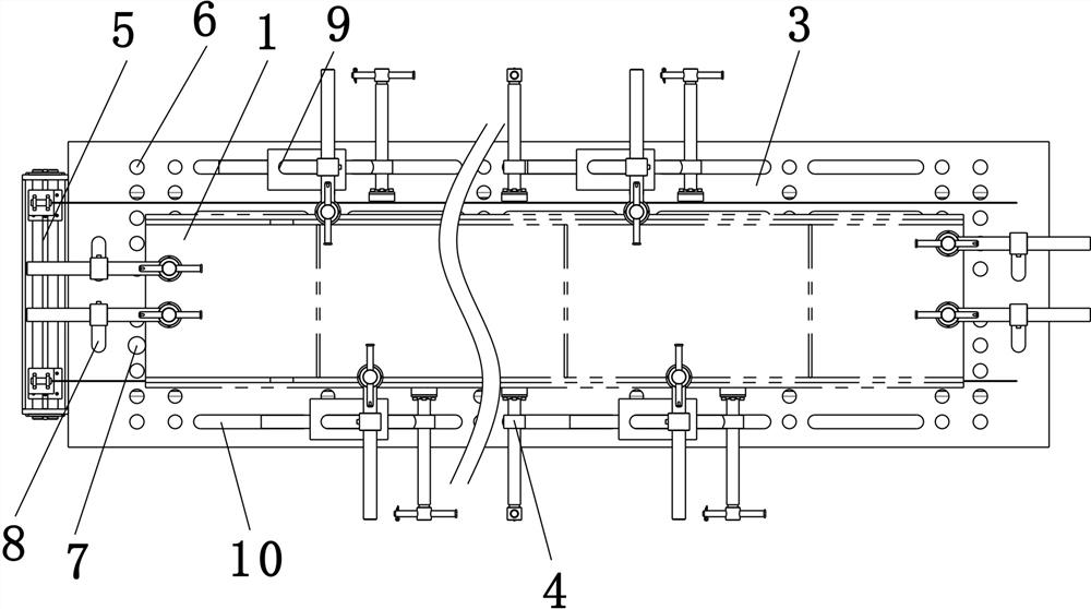
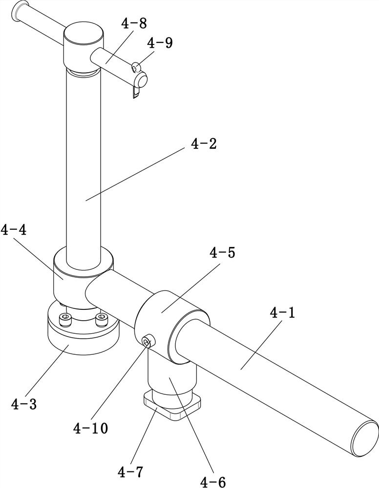
[0030] combined with Figure 1~4 , a welding process platform with a scribing device, including a box girder 1 spliced ​​by a cover plate 1-1, a web plate 1-2 and a rib plate 1-3, and also includes a frame body 2 and a platform plate 3 , a pressing device 4 and a laser-assisted positioning device 5; the surface of the cover plate 1-1 is provided with a plurality of vertical ribs 1-3 corresponding to the cover plate 1-1 at intervals along the length direction of the cover plate 1-1, and the cover plate 1-1 Both sides of the plate surface of the plate 1-1 are provided with webs 1-2 corresponding to the cover plate 1-1, and the ribs 1-3 are in vertical contact with the webs 1-2; the top of the frame body 2 is provided with There is a platform board 3, a plu...


PUM


Abstract

The invention relates to a welding process platform with a marking device in the technical field of welding tools. The welding process platform comprises a box girder formed by correspondingly splicing a cover plate, web plates and rib plates, and further comprises a frame body, a platform plate, a pressing device and a laser auxiliary positioning device; the plurality of rib plates perpendicularto the cover plate are arranged on the plate surface of the cover plate at intervals in the length direction of the cover plate, the web plates perpendicular to the cover plate are arranged on two sides of the plate surface of the cover plate, and the rib plates are in corresponding vertical contact with the web plates; and the platform plate is arranged at the top of the frame body, a plurality of positioning holes are arrayed on the periphery, close to the edge, of the plate surface of the platform plate, the cover plate is horizontally arranged on the plate surface of the platform plate, and a plurality of positioning pins correspondingly inserted into the corresponding positioning holes are respectively arranged at one end and one side, corresponding to the cover plate, of the plate surface of the platform plate. According to the welding process platform, the labor intensity of workers is effectively reduced, the positioning accuracy is high, and the operation efficiency is high.

Description

technical field [0001] The invention relates to the field of welding tooling technology, in particular to a welding process platform with a scribing device. Background technique [0002] As is well known, currently in the manufacturing process of spliced ​​end beams of cranes, when assembling slotted end beams and connecting beams, due to the large size of the plates, the amount of deformation in the natural state is also large, and the operator usually needs manual assistance when splicing and assembling. The crowbar aligns the panels to the position line, resulting in high labor intensity for operators, low efficiency, and poor splicing accuracy. Most of the finished products after welding need to be corrected, and the operation steps are cumbersome; When the beam box is placed on the level ground, the operator is in a squatting or bending state for a long time, which will cause great damage to the human body. This phenomenon is an urgent problem to be solved by those skil...

Claims


Application Information

Patent Timeline
Patent Type & Authority Applications(China)
IPC IPC(8): B23K37/04B23K37/00
CPCB23K37/0461B23K37/00Y02P70/50
Inventor 雷金柱康世创王京伟史之杰祝艺菘郑鹏
Owner NUCLEON XINXIANG CRANE
Learn More