
Precision adjusting device suitable for optical parametric oscillator

An optical parametric oscillator, precision adjustment technology, applied in lasers, laser parts, optics, etc., to ensure horizontal stability and not easy to loosen

Active Publication Date: 2021-01-15
ZHEJIANG DEYANG TECH INSTR CO LTD
View PDF10 Cites 0 Cited by
  • Summary
  • Abstract
  • Description
  • Claims
  • Application Information

AI Technical Summary

Problems solved by technology

The existing deflection angle adjustment method adopts the adjustment between threads. Although it can be adjusted in all directions without dead angles, in the actual adjustment process, the initial deflection angle does not require a large offset. A large offset error will be formed after the optical path length, so a more precise and stable adjustment method is required, so that the refraction and reflection of light can be fine-tuned to meet the needs of use

Method used


Image

  • Precision adjusting device suitable for optical parametric oscillator
  • Precision adjusting device suitable for optical parametric oscillator
  • Precision adjusting device suitable for optical parametric oscillator

Examples


Embodiment Construction

[0040] In order to more clearly describe the embodiments of the present invention and the technical solutions in the prior art, the specific embodiments of the present invention will be described below with reference to the accompanying drawings. Obviously, the accompanying drawings in the following description are only some embodiments of the present invention. For those of ordinary skill in the art, other drawings can also be obtained from these drawings without any invasive labor. and get other implementations. In addition, the belonging of the design orientation only indicates the relative positional relationship between the components, not the absolute positional relationship.

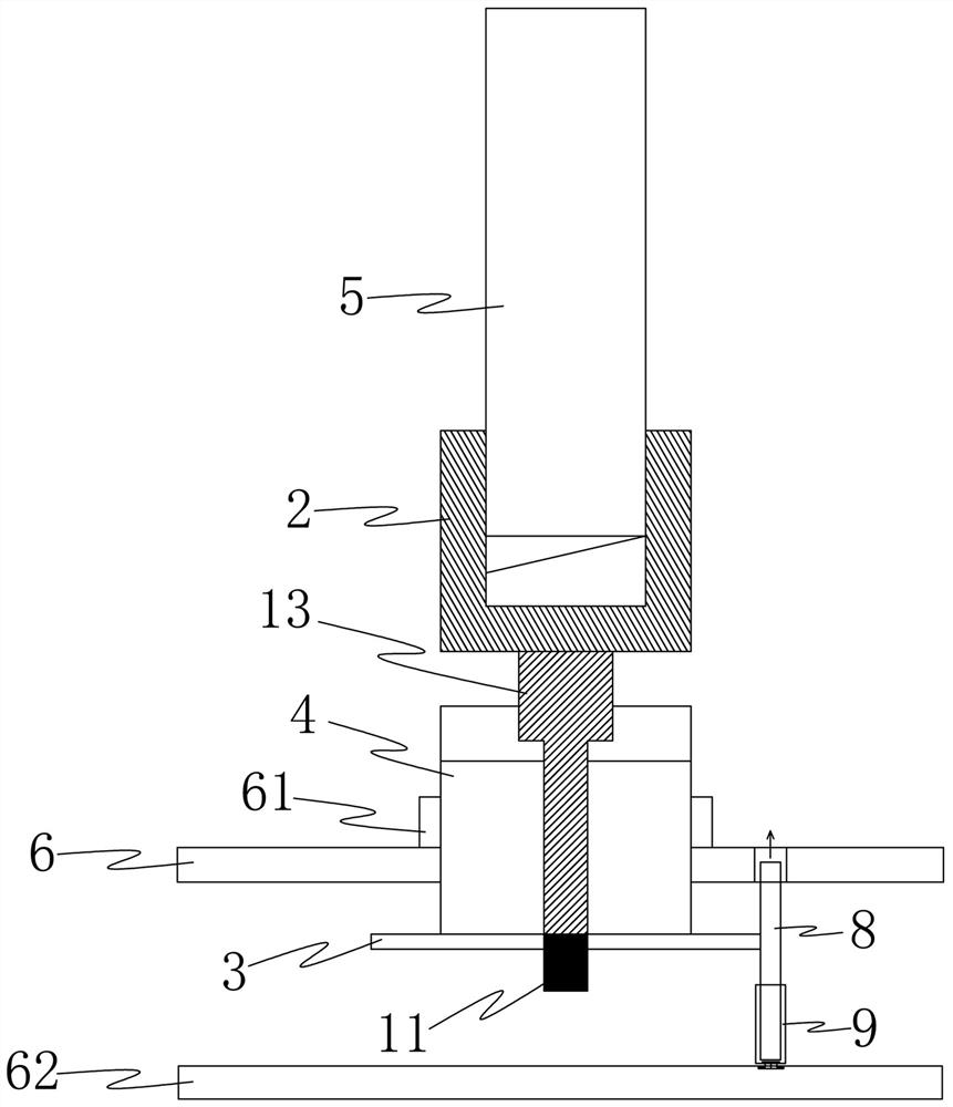
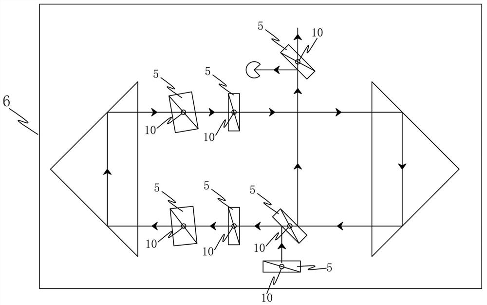
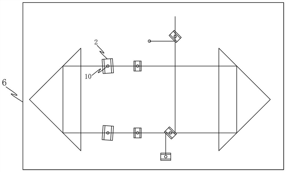
[0041] An embodiment of the present invention provides a precise adjustment device suitable for an optical parametric oscillator. Please refer to figure 1 , figure 2 , image 3 , Figure 4 , Figure 5 , Image 6 , Figure 7 , Figure 8 , Figure 9 , Figure 10 , Figure 11 , Figure 1...


PUM


Abstract

The invention provides a precision adjusting device suitable for an optical parametric oscillator. The device comprises a transmission rod, a transmission disc, a fixing piece, a lead screw and an adjusting sleeve, the adjusting sleeve is in threaded connection with the bottom, provided with a threaded part, of the lead screw, the bottom of the adjusting sleeve is rotationally connected with the fixing piece, and a guide rod is arranged at the end, located in the adjusting sleeve, of the fixing piece; the guide rod is inserted into the lead screw, inclined lines on the upper portion, providedwith inclined line parts, of the lead screw are meshed with vertical lines on the short section of the transmission disc, the transmission disc is connected with the bottom end of the transmission rod, the upper end of the transmission rod is fixedly connected with a clamp used for installing a loaded object, the adjusting sleeve is rotated, and the lead screw moves in the axis direction of the guide rod; the inclined lines on the upper portion of the lead screw can push the short-section vertical lines at the meshing position of the inclined line parts and the transmission disc so as to rotate the transmission disc, and therefore the deviation angle of the loaded object can be adjusted. According to the invention, through multiple screw-thread fit on the lead screw, the adjustment precision is amplified, and precision adjustment can be stably realized, so that the angle deviation adjustment of the loaded crystal can be stable and controllable.

Description

technical field [0001] The invention relates to the technical field of optical parametric oscillators, in particular to a precise adjustment device suitable for optical parametric oscillators. Background technique [0002] An optical parametric oscillator is a parametric oscillator that oscillates at an optical frequency. It converts the input laser light (the so-called pump light) into two lower frequency output lights (signal light and idler light) through second-order nonlinear optical interaction (crystal), the two output light The sum of frequencies is equal to the input optical frequency. Light will be refracted when passing through the crystal. If there is only one crystal, lasers of different frequencies need to rotate at different angles corresponding to the crystal. Different crystal angles mean that the position of the emitted light will change, which is not conducive to subsequent use. It is generally necessary to use a pair or several pairs of crystals to adju...

Claims


Application Information

Patent Timeline
Patent Type & Authority Applications(China)
IPC IPC(8): H01S3/108G02F1/35G02F1/39
CPCG02F1/3501G02F1/39H01S3/1083
Inventor 朱勇波
Owner ZHEJIANG DEYANG TECH INSTR CO LTD
Learn More