A new energy vehicle charging gun

A new energy vehicle, charging gun technology, applied in electric vehicle charging technology, charging stations, electric vehicles and other directions, can solve the problems of charging interruption, insufficient connection, charging gun detachment, etc., to achieve the effect of improving the fixed effect

Inactive Publication Date: 2021-10-26
厦门市晶锐永兴塑胶有限公司
View PDF6 Cites 0 Cited by
  • Summary
  • Abstract
  • Description
  • Claims
  • Application Information

AI Technical Summary

Problems solved by technology

[0003] When charging new energy vehicles, a charging gun is needed, and the car is charged by plugging the charging gun with the charging hole of the car. In the prior art, the connection between the charging gun and the charging hole of the car Not tight enough, susceptible to external factors (such as people accidentally kicking and tripping the charging cable), causing the charging cable to detach from the car charging hole, resulting in interruption of charging

Method used


Image

  • A new energy vehicle charging gun
  • A new energy vehicle charging gun
  • A new energy vehicle charging gun

Examples


Embodiment 1

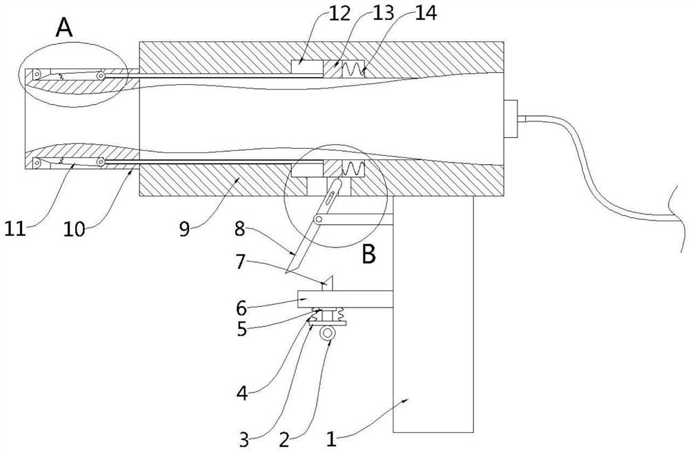
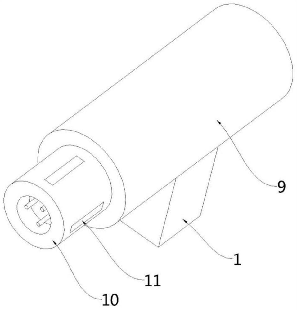
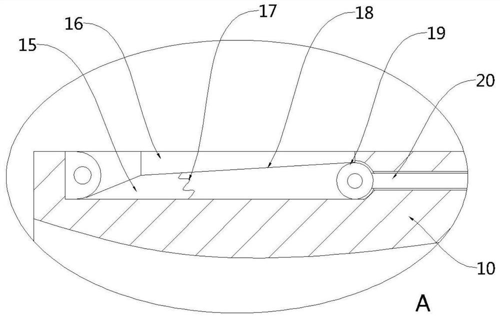
[0025] see Figure 1-4 , this embodiment provides a new energy vehicle charging gun, including a gun body 9, a handle 1 is fixedly arranged on one side of the bottom of the gun body 9, a charging head 10 is provided at one end of the gun body 9, and the outer wall of the charging head 10 is movable Several clamping parts 11 distributed in the circumferential direction are installed, and the side of the handle 1 facing the charging head 10 is provided with a device for driving the clamping parts 11 to protrude from the charging head 10 to abut against the charging hole of the car The driving part of the inner wall; specifically, the clamping part 11 includes a clamping plate 16 rotatably mounted on the outer wall of the charging head 10, and the clamping plate 16 has a first slope 18 on the side facing the charging head 10; the driving The part includes a fixed rod 22 fixedly installed on the side of the handle 1 facing the charging head 10 and a rotating rod 8 arranged at the ...

Embodiment 2

[0032] see figure 1 , a charging gun for new energy vehicles. Compared with Embodiment 1, the end of the handle 1 facing the charging head 10 in this embodiment is also provided with a limit assembly for preventing the reverse rotation of the rotating rod 8. Through the setting of the limit assembly, when the rotating rod 8 drives the clamping plate 16 to rotate outward and abut against the inner wall of the charging hole of the car, the position of the rotating rod 8 can be limited to prevent the rotating rod 8 from being under the action of the third elastic body 17 The rotating rod 8 is forced to rotate in the opposite direction, thereby causing the clamping plate 16 to be automatically retracted, so that the cooperation effect between the charging head 10 and the charging hole of the car is reduced.

[0033] Specifically, the limiting assembly includes a fixed plate 6 fixedly arranged on the side wall of the handle 1 and a movable stop rod 7 vertically penetrating through ...


PUM


Abstract

The invention provides a new energy vehicle charging gun, which belongs to the technical field of new energy, and includes a gun body, a handle is fixed on one side of the bottom of the gun body, a charging head is provided at one end of the gun body, and a charging head is movably installed on the outer wall of the charging head. A plurality of clamping parts distributed in the circumferential direction, the side of the handle facing the charging head is provided with a driving part for driving the clamping parts to protrude from the charging head to abut against the inner wall of the charging hole of the car. In the embodiment of the present invention, during the charging process of the car, the driving part drives the clamping part to protrude from the charging head to abut against the inner wall of the charging hole of the car, thereby realizing the position limitation between the charging head and the charging hole of the car, thereby improving It ensures the fixing effect between the charging head and the car charging hole, prevents the charging head from being separated from the inside of the car charging hole for no reason during the charging process of the car, and ensures that the charging process will not be interrupted.

Description

technical field [0001] The invention belongs to the technical field of new energy, in particular to a charging gun for a new energy vehicle. Background technique [0002] With the continuous development of our society and the continuous improvement of the domestic economic level, our residents' awareness of environmental protection has gradually increased, and their demand for low-carbon life and low-carbon economy has become increasingly strong. Therefore, for the automotive industry, people are urgently seeking new solutions engine technology to replace the traditional internal combustion engine technology. [0003] When charging new energy vehicles, a charging gun is needed, and the car is charged by plugging the charging gun with the charging hole of the car. In the prior art, the connection between the charging gun and the charging hole of the car It is not tight enough, and it is easy to be affected by external factors (such as people accidentally kicking and tripping...

Claims


Application Information

Patent Timeline
Patent Type & Authority Patents(China)
IPC IPC(8): H01R13/639H01R13/629B60L53/16
CPCB60L53/16H01R13/62933H01R13/639H01R2201/26Y02T10/70Y02T10/7072Y02T90/14
Inventor 郑杰
Owner 厦门市晶锐永兴塑胶有限公司
Why Eureka
Try Eureka