
A sealing device with self-cleaning function for brushless fan casing

A sealing device and self-cleaning technology, which is applied to the components of the pumping device for elastic fluid, pump device, mechanical equipment, etc., can solve the corrosion damage of internal parts of the brushless fan, reduce the service life of the brushless fan, and reduce The problem of reducing the air supply pressure of the brush fan, etc., can reduce energy consumption, improve service life, and avoid blockage.

Active Publication Date: 2022-05-13
湖南伟力汽车零部件有限公司
View PDF7 Cites 0 Cited by
  • Summary
  • Abstract
  • Description
  • Claims
  • Application Information

AI Technical Summary

Problems solved by technology

[0002] When the brushless fan is working, the vibration generated by it makes the connection between the brushless fan casing and the end cover loose, which leads to a decrease in the resistance between the brushless fan casing and the end cover, which in turn makes the external water liquid and dust enter the interior of the brushless fan, and then corrode and damage the internal parts of the brushless fan, reducing the service life of the brushless fan
Moreover, when the brushless fan is working, the air is transported from the end of the brushless fan to the main shaft through the fan blades. After the airflow passes through the net cover, the dust particles in the air will adhere to the outer surface of the net cover, causing the net cover to be damaged. The outer surface is blocked, which leads to a decrease in the air delivery pressure of the brushless fan, thereby reducing the air delivery efficiency and increasing energy consumption. In view of this, we propose a self-cleaning sealing device for the brushless fan casing

Method used


Image

  • A sealing device with self-cleaning function for brushless fan casing
  • A sealing device with self-cleaning function for brushless fan casing
  • A sealing device with self-cleaning function for brushless fan casing

Examples


Embodiment Construction

[0021] The following will clearly and completely describe the technical solutions in the embodiments of the present invention with reference to the accompanying drawings in the embodiments of the present invention. Obviously, the described embodiments are only some, not all, embodiments of the present invention. Based on the embodiments of the present invention, all other embodiments obtained by persons of ordinary skill in the art without creative efforts fall within the protection scope of the present invention.

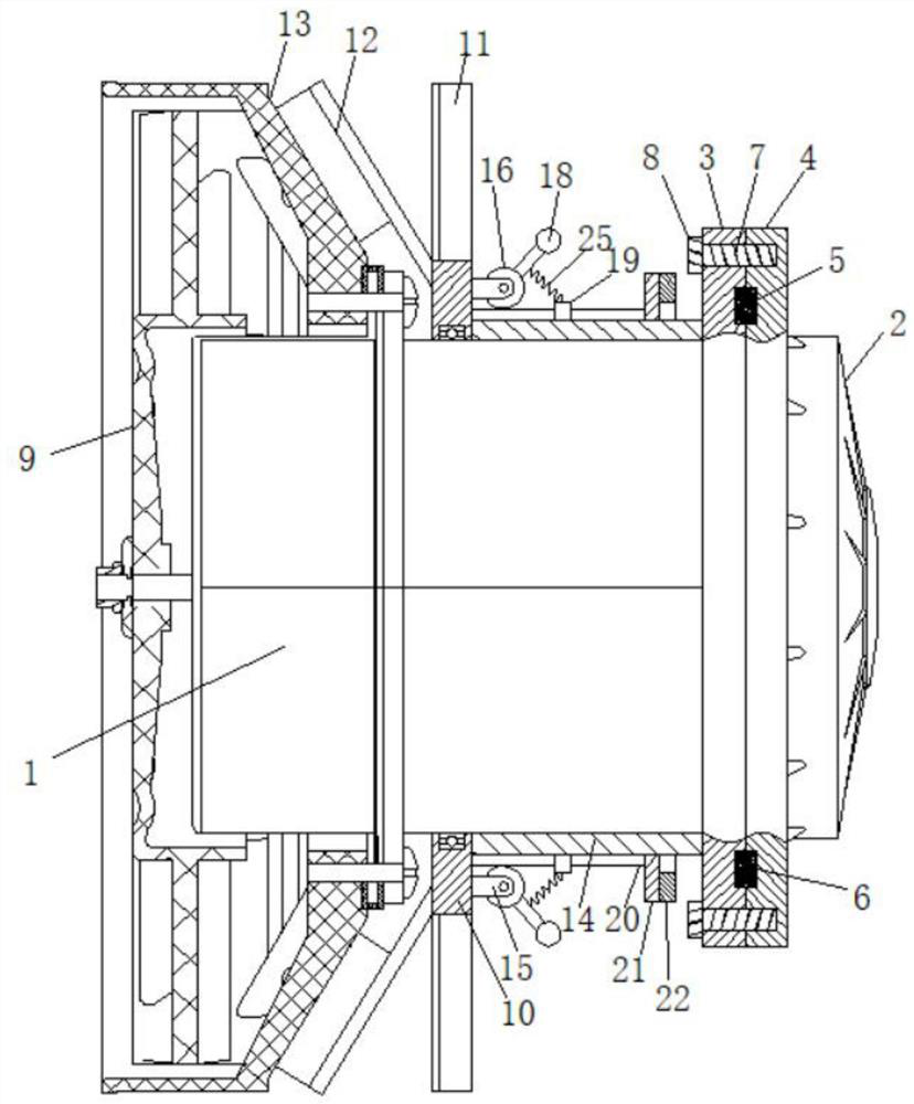
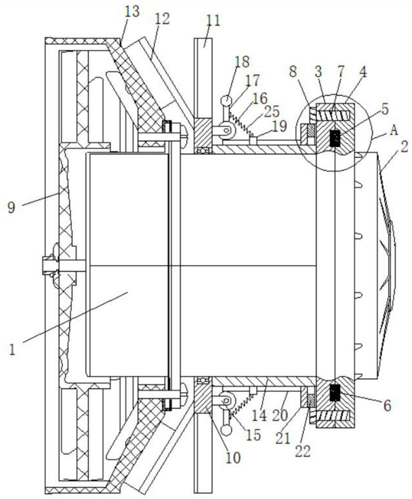
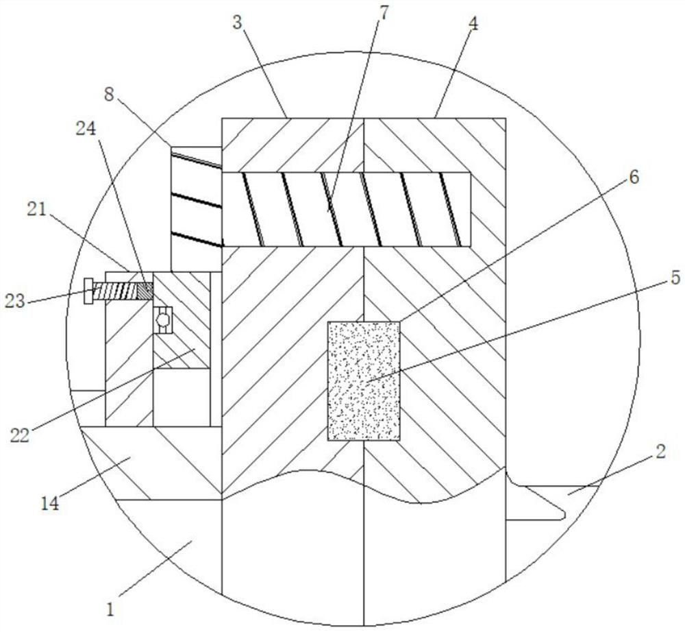
[0022] see Figure 1 to Figure 4 , the present invention provides a technical solution: a sealing device with self-cleaning function for a brushless fan casing, including a casing 1, an end cover 2, fan blades 9 and a mesh cover 13, the casing 1 and the end cover 2 are opposite The ends are respectively fixed with an outer convex ring 1 3 and an outer convex ring 2 4, the outer convex ring 1 3 and the outer convex ring 2 4 are fixedly connected by a plurality of bo...


PUM


Abstract

The invention relates to the field of brushless fan, in particular to a sealing device with self-cleaning function for the casing of a brushless fan, including a casing, an end cover, fan blades and a net cover, and the opposite ends of the casing and the end cover are respectively fixed with protruding Ring 1 and outer convex ring 2, outer convex ring 1 and outer convex ring 2 are fixedly connected by a plurality of bolts 1, the end of bolt 1 close to outer convex ring 1 is fixedly connected to gear 1, and a ring plate is sleeved on the shell, and the ring plate A plurality of leaf plates are fixed on the peripheral wall, and a plurality of brush strips are fixed on the side of the ring plate close to the net cover. The ring plate is provided with a centrifugal push-pull mechanism. It can be meshed with multiple gears at the same time. The casing of this brushless fan uses a sealing device with self-cleaning function to realize automatic cleaning of the grille, maintain stable air delivery pressure and high air delivery efficiency of the brushless fan, reduce energy consumption, and ensure that the casing and end cover are The tightness between them prevents external moisture and dust from entering the inside of the shell.

Description

technical field [0001] The invention relates to the field of brushless fans, in particular to a self-cleaning sealing device for a brushless fan casing. Background technique [0002] When the brushless fan is working, due to the vibration generated by it, the connection between the brushless fan casing and the end cover becomes loose, which leads to a decrease in the resistance between the brushless fan casing and the end cover, which in turn makes the external water liquid and dust enter the interior of the brushless fan, which will corrode and damage the internal parts of the brushless fan and reduce the service life of the brushless fan. Moreover, when the brushless fan is working, the air is transported from the tail end of the brushless fan to the main shaft end through the fan blades. After the airflow passes through the grille, the dust particles in the air will adhere to the outer surface of the grille, causing the grille to be damaged. The outer surface is blocked,...

Claims


Application Information

Patent Timeline
Patent Type & Authority Patents(China)
IPC IPC(8): F04D25/08F04D29/00F04D29/08F04D29/52F04D29/64F04D29/66F04D29/70
CPCF04D25/08F04D29/703F04D29/646F04D29/522F04D29/668F04D29/083F04D29/002
Inventor 杨浩
Owner 湖南伟力汽车零部件有限公司
Learn More